
Page 246 - MEMS Mechanical Sensors
P. 246
9.4 Force Transfer Flow Sensors 235
A general disadvantage of the drag force flow sensors is the possible damage
through high-speed particles, which can destroy the petit paddle suspension, or
low-speed particles, which clog the fluid pathway and block the paddle in case of
in-plane sensor arrangement. There is a trade-off between robustness and sensitivity
of the sensor. It is difficult to imagine this sensor being applied in harsh environ-
ments like car engines. Sensors do not induce heat to the fluid, which is advanta-
geous in some applications, as mentioned in the last section, and the chip size is
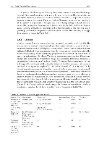
generally smaller than the pressure difference flow sensors. Data for drag force type
flow sensors is shown in Table 9.5.
9.4.2 Lift Force
Another type of flow-force sensor has been presented by Svedin et al. [94, 95]. The
silicon chip to measure bidirectional gas flow rates consists of a pair of bulk-
micromachined torsional airfoil plates connected to a center support beam as shown
in Figure 9.27. Each plate is suspended from the center support beam by two flexible,
stress-concentrating beams containing polysilicon piezoresistor on either side to
detect the deflection of the plates. The strain gauges are connected in a Wheatstone
bridge. The output of the Wheatstone bridge measuring the differential deflection is
proportional to the square of the flow velocity. The center beam is connected to two
side supports, which are used to fix the sensor in the flow stream. The sensor is
2
mounted at an optimum angle of 22° in a flow channel of 16 × 16 mm . If the
mounting angle becomes too large, the viscous drag force dominates with the result
that the deflection of both airfoil plates becomes symmetric. The lift force principle is
based on fundamental airfoil theory, and the generated force acts perpendicular to
the flow. Due to the nonuniform lift force distribution, the airfoil plates are deflected
in the same direction, but with different magnitudes. Measurements have shown that
the upstream plate was deflected about five times more than the downstream plate
(Figure 9.28). Owing to the symmetric design, the devices are insensitive to accelera-
tion forces. Data for the lift force type flow sensor are given in Table 9.6.
Table 9.5 Data for Drag Force Type Flow Sensors
Author; Year Flow Range Sensitivity Response Time Fluid Chip Size
Nishimoto et 0–140 µl/min 1.5 (µV/V)/(µl/min) — Water —
al. [86]; 1994
Gass et al. 5–500 µl/min 4.3 (µV/V)/(µl/min) — Water —
[88]; 1993
Su et al. [90]; — (∆R/R)/y(0) — Air —
–6
1996 0.23–2.91 × 10 nm –1
Zhang et al. 10–200 ml/min for — — Air 3.5 × 3.5 mm 2
[89]; 1997 200-µm gap;
3–35 ml/min for
50-µm gap
Ozaki et al. A few — — Air —
[91]; 2000 centimeters per
second to 2 m/s
Fan et al. [92, 0.2–0.9 m/s — — Water —
93]; 2002.
Chen et al.
[66]; 2003