
Page 251 - MEMS Mechanical Sensors
P. 251
240 Flow Sensors
Pipe
Flow
Epoxy Silicon
R1 R2
U1(t) U2(t)
U(t)
Electrode grid
(a) (b)
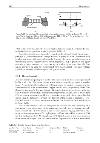
Figure 9.32 Schematics of the electrohydrodynamic flow sensor. (a) The grid size is 2.5 × 2.5
2
2
mm . The orifices in the 35-µm-thick grid structure are 100 × 100 µm . The grid distance is 10 to
60 µm. (After: [99].) (b) Double injector. (After: [94].)
300V with a repetition rate of 1 Hz was applied between the grids. Data for the elec-
trohydrodynamic type flow sensor is given in Table 9.9.
Since this measurement principle is based on the electrohydrodynamic micro-
pump [100], where the injected charges are used to pump the liquid, the sensor itself
produces pressure, which can influence the flow rate. To reduce such disturbances, a
symmetrical double injector was proposed [Figure 9.32(b)]. It produces two equal
opposite pressure components compensating each other. At the same time, the flow
sensor can now be used for bidirectional flow measurement. The high voltages
needed are a serious disadvantage of this type of sensor.
9.5.2 Electrochemical
A somewhat similar principle is used by the electrochemical flow sensor published
by Wu et al. [101]. The sensor uses an in-situ electrochemically produced molecular
tracer. An upstream electrochemical cell functions as an oxygen producer, and the
downstream cell as an amperometric oxygen sensor. Since the geometry of the flow
channel is known, the flow rate is derived from the time difference between the sig-
nals. Unlike the time of flight flow sensors using thermal tracers, there is no need for
delicate microstructures to avoid heat conduction to the wall of the channel in this
sensor since the diffusion of oxygen into the wall of the channel is negligible. How-
ever, this sensor is restricted to aqueous solutions. A schematic of the sensor is given
in Figure 9.33.
Two electrochemical cells are integrated in the flow channel consisting of a
platinum working electrode, a platinum counter electrode, and a reference electrode
made of silver. The silver electrode can be set up as a pseudo Ag/AgCl reference elec-
−
trode as the concentration of Cl in phosphate buffered saline (PBS) is constant. PBS
(in this publication: 0.04 M phosphate, 4.5% NaCl) is one of the most common
solutions in bioanalysis. The cells are connected to potentiostats. Upon application
Table 9.9 Data for Electrohydrodynamic Flow Sensor
Author; Year Flow Range Sensitivity Response Time Fluid Chip Size
Richter et al. 8–50 µl/min — — Ethanol 4 × 4mm 2
[99]; 1991 8–1,700 µl/min — — Deionized water