
Page 250 - MEMS Mechanical Sensors
P. 250
9.5 Nonthermal Time of Flight Flow Sensors 239
Mounting part
(to turbine wheel)
Blades Strain gauge
Wheel
axis
Stiffness
reduction
beam
Blades
Top view α w Pipe
of blades wall
Supporting
Flow Static turbine Insert for part
torque sensor
(a) wheel (b) (c)
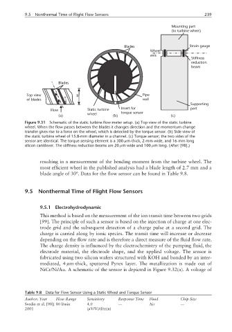
Figure 9.31 Schematic of the static turbine flow meter setup. (a) Top view of the static turbine
wheel. When the flow passes between the blades it changes direction and the momentum change
transfer gives rise to a force on the wheel, which is detected by the torque sensor. (b) Side view of
the static turbine wheel of 15.8-mm diameter in a channel. (c) Torque sensor; the two sides of the
sensor are identical. The torque-sensing element is a 300-µm-thick, 2-mm-wide, and 16-mm-long
silicon cantilever. The stiffness reduction beams are 20 µm wide and 100 µm long. (After: [98].)
resulting in a measurement of the bending moment from the turbine wheel. The
most efficient wheel in the published analysis had a blade length of 2.7 mm and a
blade angle of 30°. Data for the flow sensor can be found in Table 9.8.
9.5 Nonthermal Time of Flight Flow Sensors
9.5.1 Electrohydrodynamic
This method is based on the measurement of the ion transit time between two grids
[99]. The principle of such a sensor is based on the injection of charge at one elec-
trode grid and the subsequent detection of a charge pulse at a second grid. The
charge is carried along by ionic species. The transit time will increase or decrease
depending on the flow rate and is therefore a direct measure of the fluid flow rate.
The charge density is influenced by the electrochemistry of the pumping fluid, the
electrode material, the electrode shape, and the applied voltage. The sensor is
fabricated using two silicon wafers structured with KOH and bonded by an inter-
mediated, 4-µm-thick, sputtered Pyrex layer. The metallization is made out of
NiCr/Ni/Au. A schematic of the sensor is depicted in Figure 9.32(a). A voltage of
Table 9.8 Data for Flow Sensor Using a Static Wheel and Torque Sensor
Author; Year Flow Range Sensitivity Response Time Fluid Chip Size
Svedin et al. [98]; 80 l/min 4.0 — Air —
2001 (µV/V)/(l/min)