
Page 254 - MEMS Mechanical Sensors
P. 254
9.8 Flow Imaging 243
Sensing resistor
0.4 Opening angle = 70º
Opening angle = 110º
[Hz] 0.3
frequency 0.2
Fluid flow
Flapping 0.1
Opening 0.0
angle
0.0 1.0 2.0 3.0 4.0
Velocity [mm/s]
(a) (b)
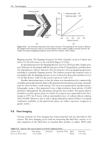
Figure 9.35 (a) Schematic drawing of the sensor structure. The opening of the nozzle is 360 µm,
the height of the structure is 48 µm, and the distance from nozzle to plate is around 2.8 mm. (b)
Graph showing the flapping frequency versus the flow velocity. (After: [103].)
flapping motion. The flapping frequency for flow velocities of up to 4 mm/s was
below 0.2 Hz with water as the test fluid [Figure 9.35(b)].
As an explanation for the flapping motion, Lee et al. [103] say that a larger pres-
sure field may be developed with the presence of the V-shaped plate, and therefore,
the impinging jet column interacts with the pressure wave propagating upstream,
resulting in a periodic flapping motion. The authors propose the required work to
investigate why the flapping motion occurs at those low Reynolds numbers (0.2 to
5.4 for this device). Data for the sensor is given in Table 9.12.
Another interesting aspect is that the sensor was manufactured in commercially
available quartz photomask plates with unpatterned chromium and resist, normally
used for electron-beam mask writing. The resist was patterned by standard photo-
lithography using a film generated from a high-resolution laser plotter (10,000
dot/inch). Subsequently the chromium and quartz were etched. The quartz plate is
bonded to another quartz plate (on which the resistors were patterned in the chro-
mium) at 50°C for 8 hours with an intermediate layer of sodium silicate solution
(SiO :NaOH). However, this is only a cheap fabrication option if there is no metal
2
evaporator available, as the photomask plates are rather expensive compared to
quartz wafers.
9.8 Flow Imaging
Various methods for flow imaging have been proposed and are described in this
section. The flow imaging can be used for measuring the fluid flow velocity or to
take snapshots of the fluid flow to visualize flow profiles or eddies. With some
Table 9.12 Data for Flow Sensor Based on Periodic Flapping Motion
Author; Year Flow Range Sensitivity Response Time Fluid Chip Size
Lee et al. [103]; 2002 >0.15 mm/s — — Water 3 × 6mm 2