
Page 253 - MEMS Mechanical Sensors
P. 253
242 Flow Sensors
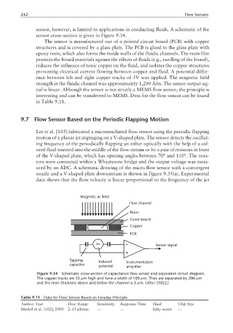
sensor, however, is limited to applications in conducting fluids. A schematic of the
sensor cross-section is given in Figure 9.34.
The sensor is manufactured out of a printed circuit board (PCB) with copper
structures and is covered by a glass plate. The PCB is glued to the glass plate with
epoxy resin, which also forms the inside walls of the fluidic channels. The resin film
protects the board materials against the effects of fluids (e.g., swelling of the board),
reduces the influence of toxic copper on the fluid, and isolates the copper structures
preventing electrical current flowing between copper and fluid. A potential differ-
ence between left and right copper tracks of 5V was applied. The magnetic field
strength in the fluidic channel was approximately 1,200 A/m. The sensor output sig-
nal is linear. Although the sensor is not strictly a MEMS flow sensor, the principle is
interesting and can be transferred to MEMS. Data for the flow sensor can be found
in Table 9.11.
9.7 Flow Sensor Based on the Periodic Flapping Motion
Lee et al. [103] fabricated a micromachined flow sensor using the periodic flapping
motion of a planar jet impinging on a V-shaped plate. The sensor detects the oscillat-
ing frequency of the periodically flapping jet either optically with the help of a col-
ored fluid inserted into the middle of the flow stream or by a pair of resistors in front
of the V-shaped plate, which has opening angles between 70° and 110°. The resis-
tors were connected within a Wheatstone bridge and the output voltage was meas-
ured by an ADC. A schematic drawing of the micro flow sensor with a convergent
nozzle and a V-shaped plate downstream is shown in Figure 9.35(a). Experimental
data shows that the flow velocity is linear proportional to the frequency of the jet
Magnetic ac field
Flow channel
Resin
Cover board
Copper
PCB
Sensor signal
Tapping Induced Instrumentation
capacitor potential amplifier
Figure 9.34 Schematic cross-section of capacitance flow sensor and equivalent circuit diagram.
The copper tracks are 35 µm high and have a width of 100 µm. They are separated by 200 µm
and the resin thickness above and below the channel is 5 µm. (After: [102].)
Table 9.11 Data for Flow Sensor Based on Faraday Principle
Author; Year Flow Range Sensitivity Response Time Fluid Chip Size
Merkel et al. [102]; 2000 2–15 µl/min — — Salty water —