
Page 255 - MEMS Mechanical Sensors
P. 255
244 Flow Sensors
techniques it can be used to follow the motion of fluids within a silicon chip, for
example, to show the droplet formation within an inkjet printer nozzle [104] or the
spinning of a microrotor [105]. For true flow velocity measurement, the flow imag-
ing technique is rather expensive due to high equipment costs and the requirement of
extensive computation. Therefore, it may only be used for specialized applications,
where not only the flow velocity but also the flow profile is of interest. For measured
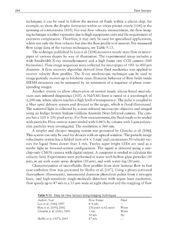
flow range data of the various techniques, see Table 9.13.
The technique published by Leu et al. [104] measures steady-state flow in micro-
pipes of various shapes by way of illustration. The experimental setup includes a
wide bandwidth X-ray monochromator and a high frame rate CCD camera (160
frames/sec). Flow image sequences were collected for micropipes of 100- to 400-µm
diameter. A flow recovery algorithm derived from fluid mechanics was applied to
recover velocity flow profiles. The X-ray stroboscopic technique can be used to
image periodic motion up to kilohertz rates. Dynamic behavior of flow fields inside
MEMS structures can be measured by an animation of a sequence of phase corre-
sponding images.
Another system to allow observation of motion inside silicon-based microde-
vices uses infrared diagnostics [105]. A Nd:YAG laser is tuned to a wavelength of
1,200 nm, where silicon reaches a high level of transparency. The pulse is coupled to
a fiber optic delivery system and directed to the target, which is flood illuminated.
The scattered light is collected by a near-infrared microscope objective and imaged
using an Indigo System Indium Gallium Arsenide Near-Infrared camera. The cam-
era has a 320 × 256 pixel array. For flow measurements, the fluid needs to be seeded
with particles. Flow rates in water seeded with 0.06% by volume with 1-µm polysty-
rene particles were investigated. The resolution is 360 nm.
A simpler and cheaper imaging system was presented by Chetelat et al. [106].
This system can only be used for devices with an optical window. The particle image
2
velocimetry system has a field of view of 6 × 5mm and can measure 50 velocity vec-
tors for liquid flows slower than 1 m/s. Twelve super-bright LEDs are used as a
strobe light in forward-scatter configuration. The signal is detected using a one-
chip-only CMOS camera with digital output. A computer is needed to calculate the
velocity field. Experiments were performed in water with hollow glass particles (10
µm), in air with water spray droplets (50 µm), and with water fog (20 µm).
Characterization of microfluidic flow profiles from slow laminar flow to fast
near-turbulent flow was presented by Shelby et al. [107]. Using a photo-activated
fluorophore (fluorescein), nanosecond duration photolysis pulses from a nitrogen
laser, and high-sensitivity single-molecule detection with argon laser excitation,
flow speeds up to 47 m/s in a 33-µm-wide straight channel and the mapping of flow
Table 9.13 Data for Flow Sensors Using Imaging Techniques
Author; Year Flow Range Fluid
Leu et al. [104]; 1997 4–8 nl/s —
Han et al. [105]; 2002 250 µm/s to 62 mm/s Water
Chetelat et al. [106]; 2002 1 m/s Water
10 m/s Air
Shelby et al. [107]; 2003 47 m/s —