
Page 245 - MEMS Mechanical Sensors
P. 245
234 Flow Sensors
Flow
(from the front)
Flow
Paddle
Piezoresistive
elements
Beam Strain
gauge
(a) (b)
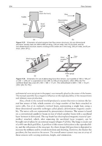
Figure 9.25 Schematics of wind receptor hair flow sensor structures: (a) one-dimensional
structure: sensory hairs are 400 to 800 µm long, 230 µm wide, and 10 µm thick; and (b)
two-dimensional structure: beams crossing at the center are 3 mm long, 250 µm wide, and 8 µm
thick. (After: [91].)
Flow
Flow
Wind
Wind receptor receptor
hair
hair
Strain
gauge
Strain gauge
(a) (b)
Figure 9.26 Schematics for out-of-plane drag force flow sensors. (a) A paddle of 100 × 100 µm 2
2
or 250 × 250 µm is suspended on two 200- to 550-µm-long beams. (After: [90].) (b) The
3
3
cantilever beam has a size of 1,100 × 180 × 17 µm . The vertical beam is 820 × 100 × 10 µm .
(After: [66, 92, 93].)
and material were not given in the paper) was manually glued to the center of the beams.
The manual assembly has a negative influence on the reproducibility of the measurement
and ultimate mass production.
Also, a look to the natural world produced a sensor that tries to imitate the lat-
eral line sensor of fish, which consists of a large number of fine hairs attached to
nerve cells. Fan et al. realized a vertical beam, representing a single hair, using a
three-dimensional assembly technique called plastic deformation magnetic assem-
bly. The nerve cells are represented by piezoresistive elements. The sensor is based
on a conventional cantilever beam on top of which another beam with a sacrificial
layer between is fabricated. The top beam has electroplated magnetic material (per-
malloy) attached, which, after removing the sacrificial layer (copper), can be
brought out-of-plane by an external magnet [Figure 9.25(b)]. The hinge is made out
of a 600-nm-thick gold film. A problem of this sensor fabrication is the reproducibil-
ity and the robustness of the structure. In a later design [66] parylene is deposited to
increase the stiffness and to avoid electrolysis and shorting. However, the thicker the
parylene, the less sensitive the sensor. The overall sensor system may use an array of
those sensors with varying positions, height, and orientation.