
Page 169 - MEMS and Microstructures in Aerospace Applications
P. 169
Osiander / MEMS and microstructures in Aerospace applications DK3181_c008 Final Proof page 159 1.9.2005 12:05pm
Microelectromechanical Systems for Spacecraft Communications 159
l 2
S in
l 1 S out
1-bit 2-bit 4-bit 8-bit
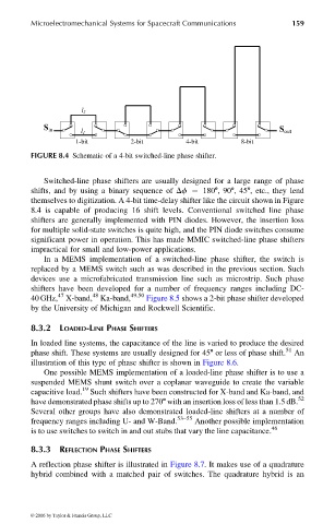
FIGURE 8.4 Schematic of a 4-bit switched-line phase shifter.
Switched-line phase shifters are usually designed for a large range of phase
shifts, and by using a binary sequence of Df ¼ 1808,908,458, etc., they lend
themselves to digitization. A 4-bit time-delay shifter like the circuit shown in Figure
8.4 is capable of producing 16 shift levels. Conventional switched line phase
shifters are generally implemented with PIN diodes. However, the insertion loss
for multiple solid-state switches is quite high, and the PIN diode switches consume
significant power in operation. This has made MMIC switched-line phase shifters
impractical for small and low-power applications.
In a MEMS implementation of a switched-line phase shifter, the switch is
replaced by a MEMS switch such as was described in the previous section. Such
devices use a microfabricated transmission line such as microstrip. Such phase
shifters have been developed for a number of frequency ranges including DC-
47 48 49,50
40 GHz, X-band, Ka-band, Figure 8.5 shows a 2-bit phase shifter developed
by the University of Michigan and Rockwell Scientific.
8.3.2 LOADED-LINE PHASE SHIFTERS
In loaded line systems, the capacitance of the line is varied to produce the desired
phase shift. These systems are usually designed for 458 or less of phase shift. 51 An
illustration of this type of phase shifter is shown in Figure 8.6.
One possible MEMS implementation of a loaded-line phase shifter is to use a
suspended MEMS shunt switch over a coplanar waveguide to create the variable
19
capacitive load. Such shifters have been constructed for X-band and Ka-band, and
have demonstrated phase shifts up to 2708 with an insertion loss of less than 1.5 dB. 52
Several other groups have also demonstrated loaded-line shifters at a number of
frequency ranges including U- and W-Band. 53–55 Another possible implementation
is to use switches to switch in and out stubs that vary the line capacitance. 46
8.3.3 REFLECTION PHASE SHIFTERS
A reflection phase shifter is illustrated in Figure 8.7. It makes use of a quadrature
hybrid combined with a matched pair of switches. The quadrature hybrid is an
© 2006 by Taylor & Francis Group, LLC