
Page 172 - MEMS and Microstructures in Aerospace Applications
P. 172
Osiander / MEMS and microstructures in Aerospace applications DK3181_c008 Final Proof page 162 1.9.2005 12:05pm
162 MEMS and Microstructures in Aerospace Applications
These systems can achieve very high directionality for sending as well as receiving.
A major advantage in spacecraft of this approach is that these systems do not
require any attitude adjustment, either to compensate for the antenna motion or to
direct the antenna. The second application is a switched antenna, where antenna
arrays are connected in a way that it matches different frequency bands. This allows
for rapid alteration between a low transmission rate to a higher frequency with
higher transmission rate. Transmission to Earth and between satellites, commonly
in different bands, could therefore be done using only one antenna array.
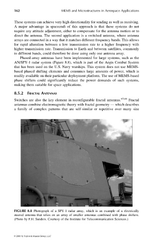
Phased-array antennas have been implemented for large systems, such as the
AN/SPY-1 radar system (Figure 8.8), which is part of the Aegis Combat System
that has been used on the U.S. Navy warships. This system does not use MEMS-
based phased shifting elements and consumes large amounts of power, which is
readily available on their particular deployment platform. The use of MEMS-based
phase shifters could significantly reduce the power demands of such systems,
making them suitable for space applications.
8.5.2 FRACTAL ANTENNAS
Switches are also the key element in reconfigurable fractal antennas. 65,66 Fractal
antennas combine electromagnetic theory with fractal geometry — which describes
a family of complex patterns that are self-similar or repetitive over many size
FIGURE 8.8 Photograph of a SPY-1 radar array, which is an example of a electrically
steered antenna that relies on an array of smaller antennas combined with phase shifters.
(Photo by F.H. Sanders. Courtesy of the Institute for Telecommunication Sciences.)
© 2006 by Taylor & Francis Group, LLC