
Page 177 - MEMS and Microstructures in Aerospace Applications
P. 177
Osiander / MEMS and microstructures in Aerospace applications DK3181_c008 Final Proof page 167 1.9.2005 12:05pm
Microelectromechanical Systems for Spacecraft Communications 167
GEO S/C
FOR
Beamwidth
Multiple or sequential
beam positions
Beam jitter
Ground
terminals
Coverage footprint
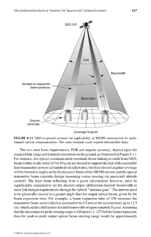
FIGURE 8.11 GEO-to-ground scenario for applicability of MEMS micromirrors to multi-
channel optical communications. The same terminal could support intersatellite links.
The two most basic requirements, FOR and angular accuracy, depend upon the
requiredlink range and terminal separationonthe ground,as illustrated inFigure8.11.
For instance, for optical communication terminals down-linking to earth from GEO,
beam widths ontheorder of 5to10 mradare desired tosupport thelink with reasonable
laser transmitter powers (at hundredsof milliwatts), but theirsteered angularcoverage
will be limited toangles set bythedynamic limitsof theMEMS mirrors and theoptical
transmitter beam expander design (assuming coarse steering via spacecraft attitude
control). The laser beam reflecting from a given micromirror, however, must be
significantly expanded to set the desired output (diffraction-limited) beamwidth to
meet link margin requirements through the optical ‘‘antenna gain.’’ The mirrors need
to be physically steered to a greater angle than the output optical beam, given by the
beam expansion ratio. For example, a beam expansion ratio of 250 increases the
transmitter beam waist (which is assumed to be 0.5 mm at the micromirror) up to 12.5
cm, which yields a diffraction-limited beamwidth of approximately8 mrad. Assuming
that themicromirrors peak steering range is420 mrad(+128) before beam expansion,
then the peak-to-peak output optical beam steering range would be approximately
© 2006 by Taylor & Francis Group, LLC