
Page 173 - MEMS and Microstructures in Aerospace Applications
P. 173
Osiander / MEMS and microstructures in Aerospace applications DK3181_c008 Final Proof page 163 1.9.2005 12:05pm
Microelectromechanical Systems for Spacecraft Communications 163
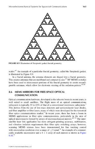
FIGURE 8.9 Illustration of Sierpinski gasket fractal geometry.
scales. 67 An example of a particular fractal geometry, called the Sierpinski gasket,
is illustrated in Figure 8.9.
In a fractal antenna, the antenna elements are shaped into a fractal geometry.
67
This creates antennas that are multiband and compact in size. RF MEMS switches
have been used to interconnect portions of the fractal geometry to create reconfi-
gurable antennas, which allow for electronic steering of the radiation pattern. 65,66
8.6 MEMS MIRRORS FOR FREE-SPACE OPTICAL
COMMUNICATION
Optical communication hardware, developed in the telecom boom in recent years, is
well suited to small satellites. The flight mass of an optical communications
3
subsystem is typically 55 to 65% of that of a conventional microwave subsystem.
This derives from the use of low-mass detectors and semiconductor laser diodes,
and fiber amplifier or fiber lasers, many of which were developed for the terrestrial
4
fiber optics communications market. In recent years, there has been a boom in
MEMS applications in fiber optic communications, particularly in the area of
optical interconnects formed by arrays of micromechanical mirrors. 68–72 The inter-
satellite laser link application has more stringent pointing accuracy, stabilization,
and vibration isolation requirements than fiber optic switching arrays; however,
scanning MEMS mirrors have been demonstrated for fine tracking control
with microradian resolution over a range of +3 mrad. 73 An example of a commer-
cially available micromirror and a 4 1 array of such mirrors is shown in Figure
8.10. 74
© 2006 by Taylor & Francis Group, LLC