
Page 178 - MEMS and Microstructures in Aerospace Applications
P. 178
Osiander / MEMS and microstructures in Aerospace applications DK3181_c008 Final Proof page 168 1.9.2005 12:05pm
168 MEMS and Microstructures in Aerospace Applications
1.7 mrad after beam expansion. An 8-mrad beamwidth produces a patch on the ground
approximately 300 m across from GEO, and the maximum steering angle will cover a
distance of approximately 60 km, corresponding to 200 beam widths. The MEMS
mirror angular accuracy should be approximately 2.7 mrad (approximately 1/3 of the
beamwidth) after beam expansion and 0.675 mrad before (corresponding to an
angular dynamic range of 28 dB). The element pitch of such a MEMS mirror array
should be adjusted in the plane of the array to enable adjacent mirrors to address
adjacent areas on the earth separated by approximately 1.7 mrad. A 4 4 array would
thus cover a square area of 240 km on a side, which is sufficient to reach terminal
locations on the ground that would likely have decorrelated weather conditions,
because weather cells are nominally approximately 250 km across. This is important
for achieving site diversity to mitigate cloud cover. 108
The closed-loop bandwidth requirement indicated in Table 8.1 is primarily set
by the expected platform vibration environment, which can be present up to 1 kHz
but is usually significant only up to approximately 100 Hz for most spacecraft. This
parameter must be considered in establishing closed-loop control. 109
A further trade-off between the transmitter power required to support the link
margin and the degree of laser heat load experienced by the array elements must
also be determined. The transmitter modulation waveform, such as pulse position
modulation (PPM) with a variable M-ary value, is an additional degree of freedom
in this trade. Under these circumstances preliminary link analyses indicate that the
required average laser transmitter power should not exceed a few hundred milli-
watts. Prior tests have suggested that the MEMX micromirrors can tolerate up to
approximately 300 mW incident laser power. However, in the MEMS design the
most efficient heat conduction path should be used, which is conduction through air
or a similar gas. Additionally, the degree of micromirror curvature under steady-
state conditions must be defined and maintained, and this is made easier at high
partial pressures. This is the principal concern for beamwidth control.
8.6.3 PERFORMANCE TESTING FOR OPTICAL BEAMSTEERING
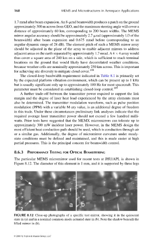
The particular MEMS micromirror used for recent tests at JHU/APL is shown in
Figure 8.12. The diameter of this element is 1 mm, and it is supported by three legs
FIGURE 8.12 Close-up photographs of a specific test mirror, showing it in the quiescent
state in (a) and in a nominal common-mode actuated state in (b). Note the shadow beneath the
lifted mirror in (b).
© 2006 by Taylor & Francis Group, LLC