
Page 181 - MEMS and Microstructures in Aerospace Applications
P. 181
Osiander / MEMS and microstructures in Aerospace applications DK3181_c008 Final Proof page 171 1.9.2005 12:05pm
Microelectromechanical Systems for Spacecraft Communications 171
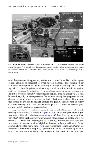
FIGURE 8.13 Optical test-bed layout to evaluate MEMX micromirror performance under
partial pressure. This overall view includes sample test results, including the beam spot on the
micromirror and at the CCD output focal plane, as well as the thermal camera image of the
micromirror.
more than adequate to support application requirements for multiaccess free-space
optical terminals on spacecraft or other moving platforms. The presence of air
around the device provides viscous damping, allowing for achieving critical damp-
ing, which is best for pointing and tracking control as well as stabilizing against
platform vibration. Investigation of the amplitude response versus pressure was
limited to pressures well above the molecular regime, since we expect the Q would
be undesirably high at lower pressures. Furthermore, at very low gas pressures, heat
dissipation would be less without the conductive heat transfer effect of the air, and
thus should be avoided to prevent damage and possible modification of mirror
curvature. Having a controlled pressure envelope around the device also mitigates
against humidity and other contamination.
Angle sensitivity was initially measured using a quad cell sensor, which for null
tracking is satisfactory, as shown in Figure 8.14(b), where the quad output signal
was heavily filtered to eliminate read-out noise. Without filtering the noise floor
was 20 mV at the quad output, which translates into an equivalent angle noise at the
mirror of 1.2 mrad. With filtering we saw much less inherent electrical noise and
were unable to measure it with a digital oscilloscope, although ambient air fluctu-
ations perturbing the micro-mirror were visibly discernable. Using a CCD array, we
were able to measure low frequency (approximately 10 Hz) sine wave inputs down
to 360 mrad, but this is not likely to be the actual intrinsic noise floor of the mirror.
© 2006 by Taylor & Francis Group, LLC