
Page 182 - MEMS and Microstructures in Aerospace Applications
P. 182
Osiander / MEMS and microstructures in Aerospace applications DK3181_c008 Final Proof page 172 1.9.2005 12:05pm
172 MEMS and Microstructures in Aerospace Applications
Even at this level, however, an appropriate beam expansion factor (M) will translate
this into a smaller angle (by 1/M), which is consistent with the requirement of 1000
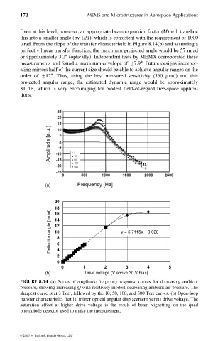
mrad. From the slope of the transfer characteristic in Figure 8.14(b) and assuming a
perfectly linear transfer function, the maximum projected angle would be 57 mrad
or approximately 3.28 (optically). Independent tests by MEMX corroborated these
measurements and found a maximum envelope of +7.98. Future designs incorpor-
ating mirrors half of the current size should be able to achieve angular ranges on the
order of +128. Thus, using the best measured sensitivity (360 mrad) and this
projected angular range, the estimated dynamic range would be approximately
31 dB, which is very encouraging for modest field-of-regard free-space applica-
tions.
(a)
20
18
Deflection angle [mrad] 14 8 y = 5.7115x − 0.028
16
12
10
2 6 4
0
0 1 2 3 4 5
(b) Drive voltage (V above 30 V bias)
FIGURE 8.14 (a) Series of amplitude frequency response curves for decreasing ambient
pressure, showing increasing Q with relatively modest decreasing ambient air pressure. The
sharpest curve is at 3 Torr, followed by the 10, 50, 100, and 500 Torr curves. (b) Open-loop
transfer characteristic, that is, mirror optical angular displacement versus drive voltage. The
saturation effect at higher drive voltage is the result of beam vignetting on the quad
photodiode detector used to make the measurement.
© 2006 by Taylor & Francis Group, LLC