
Page 284 - MEMS and Microstructures in Aerospace Applications
P. 284
Osiander / MEMS and microstructures in Aerospace applications DK3181_c012 Final Proof page 276 1.9.2005 9:13pm
276 MEMS and Microstructures in Aerospace Applications
Voids in the die-attach material cause areas of localized stress concentration
that can lead to premature delamination. Presently, MEMS packages use
solders, adhesives, or epoxies for die attach. Each method has advantages and
disadvantages that affect the overall MEMS reliability. Generally, when a solder
is used, the silicon die would have a gold backing. Au–Sn (80–20) solder generally
is used and forms an Au–Sn eutectic when the assembly is heated to approximately
2508C in the presence of a forming gas. When this method is applied, a single rigid
assembled part with low thermal and electrical resistances between the MEMS
device and the package is obtained. One problem with this attachment method
is that the solder attach is rigid (and brittle) which means it is critical for the
MEMS device and the package CTEs to match since the solder cannot absorb
the stresses.
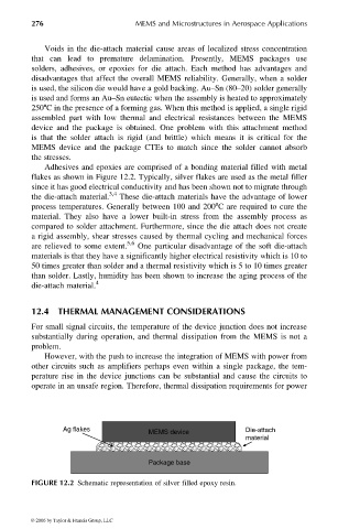
Adhesives and epoxies are comprised of a bonding material filled with metal
flakes as shown in Figure 12.2. Typically, silver flakes are used as the metal filler
since it has good electrical conductivity and has been shown not to migrate through
the die-attach material. 3,4 These die-attach materials have the advantage of lower
process temperatures. Generally between 100 and 2008C are required to cure the
material. They also have a lower built-in stress from the assembly process as
compared to solder attachment. Furthermore, since the die attach does not create
a rigid assembly, shear stresses caused by thermal cycling and mechanical forces
are relieved to some extent. 5,6 One particular disadvantage of the soft die-attach
materials is that they have a significantly higher electrical resistivity which is 10 to
50 times greater than solder and a thermal resistivity which is 5 to 10 times greater
than solder. Lastly, humidity has been shown to increase the aging process of the
die-attach material. 4
12.4 THERMAL MANAGEMENT CONSIDERATIONS
For small signal circuits, the temperature of the device junction does not increase
substantially during operation, and thermal dissipation from the MEMS is not a
problem.
However, with the push to increase the integration of MEMS with power from
other circuits such as amplifiers perhaps even within a single package, the tem-
perature rise in the device junctions can be substantial and cause the circuits to
operate in an unsafe region. Therefore, thermal dissipation requirements for power
Ag flakes Die-attach
MEMS device
material
Package base
FIGURE 12.2 Schematic representation of silver filled epoxy resin.
© 2006 by Taylor & Francis Group, LLC