
Page 285 - MEMS and Microstructures in Aerospace Applications
P. 285
Osiander / MEMS and microstructures in Aerospace applications DK3181_c012 Final Proof page 277 1.9.2005 9:13pm
MEMS Packaging for Space Applications 277
amplifiers, other large signal circuits, and highly integrated packages can place
severe design constraints on the package design. The junction temperature (T j )of an
isolated device can be determined by
T j ¼ QR þ T case (12:2)
where
Q (W) is the heat dissipated by the junction and is dependent on the output power
of the device and its efficiency,
R (8C/W) is the thermal resistance between the junction and the case, and
T case (8C) is the temperature of the case.
Normally, the package designer has no control over Q and the case temperature,
and therefore, it is the thermal resistance of the package that must be minimized.
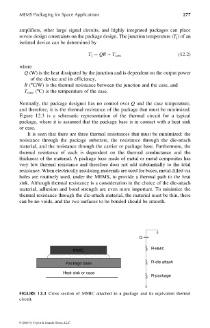
Figure 12.3 is a schematic representation of the thermal circuit for a typical
package, where it is assumed that the package base is in contact with a heat sink
or case.
It is seen that there are three thermal resistances that must be minimized: the
resistance through the package substrate, the resistance through the die-attach
material, and the resistance through the carrier or package base. Furthermore, the
thermal resistance of each is dependent on the thermal conductance and the
thickness of the material. A package base made of metal or metal composites has
very low thermal resistance and therefore does not add substantially to the total
resistance. When electrically insulating materials are used for bases, metal-filled via
holes are routinely used, under the MEMS, to provide a thermal path to the heat
sink. Although thermal resistance is a consideration in the choice of the die-attach
material, adhesion and bond strength are even more important. To minimize the
thermal resistance through the die-attach material, the material must be thin, there
can be no voids, and the two surfaces to be bonded should be smooth.
Q
MMIC R-MMIC
Package base R-die attach
Heat sink or case
R-package
FIGURE 12.3 Cross section of MMIC attached to a package and its equivalent thermal
circuit.
© 2006 by Taylor & Francis Group, LLC