
Page 370 - MEMS and Microstructures in Aerospace Applications
P. 370
Osiander / MEMS and microstructures in Aerospace applications DK3181_c016 Final Proof page 363 1.9.2005 12:56pm
Microelectromechanical Systems and Microstructures in Aerospace 363
16.5.1.3 Test Methodology
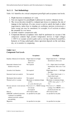
Table 16.5 identifies the critical component protoflight and acceptance test levels.
1. Flight duration or minimum of 1 min.
2. Test not required for protoflight if addressed by random vibration levels.
3. The sweep direction should be evaluated and chosen to minimize the risk of
damage to the hardware. If a sine sweep is used to satisfy the loads or other
requirements, rather than to simulate an oscillatory mission environment, a
faster sweep rate may be considered, for example, 6 to 8 oct/min to reduce
the potential for over-stress.
4. Acoustic sensitive components only.
5. Component thermal acceptance tests shall be performed in vacuum if the
component contains high junction temperature devices or high voltages
(>100 V) or vacuum-sensitive parts such as moving mechanical assemblies,
hermetic or O-ring sealed parts whose operation depends on the seal integ-
rity, or is sensitive to outgassing.
TABLE 16.5
Component Test Levels
Acceptance Protoflight
Random vibration level duration Flight (limit) level flight Flight (limit) level þ 3 dB flight
duration/axis duration/axis; three axes
three axes
Sinusoidal vibration level Not required 1.25 flight (limit) level flight
duration sweep rate duration/axis; three axes 4 oct/
min
Acoustics level duration Not required Flight (limit) level þ 3 dB flight
duration
Structural loads test analysis Not required 1.25 flight (limit) loads 1.4
flight (limit) loads
Mechanical shock analysis Not required 1.4 flight (limit) level
Thermal cycle or vacuum Maximum or minimum design Maximum or minimum design
+158C; +108C; four cycles 1 10 5
six cycles thermal cycle Torr
Pressure pressure vessel pressure Proof test (1.5 MEOP) leakage Proof test (1.5 MEOP)
profile test (meop) Leakage Test (MEOP) 1.12
not required predicted pressure rate
Burn-in 100 h total on-time 100 h total on-time
EMI/EMC conducted emissions As specified in test plan As specified in test plan
conducted susceptibility
radiated emissions radiated
susceptibility
Magnetics As specified in test plan As specified in test plan
© 2006 by Taylor & Francis Group, LLC