
Page 369 - MEMS and Microstructures in Aerospace Applications
P. 369
Osiander / MEMS and microstructures in Aerospace applications DK3181_c016 Final Proof page 362 1.9.2005 12:56pm
362 MEMS and Microstructures in Aerospace Applications
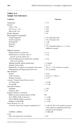
TABLE 16.4
Sample Test Tolerances
Condition Tolerance
Temperature + 3 8C
Pressure
Above 1 Torr + 10%
0.01 Torr to 1 Torr + 25%
Below 0.001 Torr + 80%
Relative Humidity + 5%
Electromagnetic Compatibility
Voltage magnitude + 5% of the peak value
Current magnitude + 5% of the peak value
RF amplitudes + 2dB
Frequency + 2%
Distance + 5% of specified distance or + 2.5 cm,
whichever is greater
Magnetic Properties
Mapping distance measurement + 1cm
Displacement of assembly center of + 5cm
gravity (cg) from rotation axis
Vertical displacement of single probe centerline + 5cm
from cg of assembly
Mapping turntable angular displacement + 3 degrees
Magnetic field strength + 0.1 nT
Repeatability of magnetic measurements (short term) + 5% or + 2 nT, whichever is greater
Demagnetizing and Magnetizing Field Level: + 5% of nominal
Mass Properties
Weight + 0.2%
Center of gravity + 0.15 cm (+ 0.06 in.)
Moments of inertia: + 1.5%
Acoustic Vibration–Sound Pressure Levels
1/3-Octave band + 3.0 dB
Overall SPL + 1.5 dB
Sinusoidal Vibration
Amplitude + 10%
Frequency (Hz) + 2%
Random Vibration Acceleration
2
RMS level power spectral density (G /Hz) 10%
20 to 500 Hz (25 Hz or narrower) + 1.5 dB
500 to 2000 Hz (50 Hz or narrower) + 3.0 dB
Random overall GRMS: + 1.5 dB
Shock Response (Q ¼ 10)
1/6 Octave band center frequency amplitude (G’s) + 6 dB with 30% of the response spectrum
center frequency amplitude greater than
nominal test specifications
0-2000 Hz >2000 Hz þ 10 dB/-6dB
Load
Static and steady-state (acceleration) + 5%
© 2006 by Taylor & Francis Group, LLC