
Page 270 -
P. 270
LIGA and Micromolding 4-11
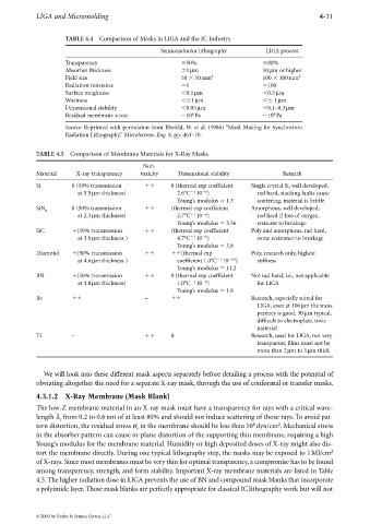
TABLE 4.4 Comparison of Masks in LIGA and the IC Industry
Semiconductor lithography LIGA process
Transparency 50% 80%
Absorber thickness 1µm 10 µm or higher
Field size 50 50mm 2 100 100mm 2
Radiation resistance 1 100
Surface roughness 0.1µm 0.5µm
Waviness 1µm 1µm
Dimensional stability 0.05µm 0.1–0.3µm
8
8
Residual membrane stress 10 Pa 10 Pa
Source: Reprinted with permission from Ehrfeld, W. et al. (1986) “Mask Making for Synchrotron
Radiation Lithography,” Microlectron. Eng. 5, pp. 463–70.
TABLE 4.5 Comparison of Membrane Materials for X-Ray Masks
Non-
Material X-ray transparency toxicity Dimensional stability Remark
Si 0 (50% transmission
0 (thermal exp coefficient Single crystal Si, well developed,
1
6
at 5.5µm thickness) 2.6°C 10 ) rad hard, stacking faults cause
Young’s modulus 1.3 scattering, material is brittle
SiN 0 (50% transmission
(thermal exp coefficient Amorphous, well developed,
x
at 2.3µm thickness) 2.7°C 10 ) rad hard if free of oxygen,
6
1
Young’s modulus 3.36 resistant to breakage
SiC
(50% transmission
(thermal exp coefficient Poly and amorphous, rad hard,
6
1
at 3.6µm thickness ) 4.7°C 10 ) some resistance to breakage
Young’s modulus 3.8
Diamond
(50% transmission
(thermal exp Poly, research only, highest
1
at 4.6µm thickness ) coefficient 1.0°C 10 66 ) stiffness
Young’s modulus 11.2
BN
(50% transmission
0 (thermal exp coefficient Not rad hard, i.e., not applicable
1
6
at 3.8µm thickness) 1.0°C 10 ) for LIGA
Young’s modulus 1.8
Be
–
Research, especially suited for
LIGA, even at 100µm the trans
parency is good, 30µm typical,
difficult to electroplate, toxic
material
Ti –
0 Research, used for LIGA, not very
transparent, films must not be
more than 2µm to 3µm thick
We will look into these different mask aspects separately before detailing a process with the potential of
obviating altogether the need for a separate X-ray mask, through the use of conformal or transfer masks.
4.3.1.2 X-Ray Membrane (Mask Blank)
The low-Z membrane material in an X-ray mask must have a transparency for rays with a critical wave-
length λ from 0.2 to 0.6nm of at least 80% and should not induce scattering of those rays. To avoid pat-
c
8
2
tern distortion, the residual stress σ in the membrane should be less than 10 dyn/cm . Mechanical stress
r
in the absorber pattern can cause in-plane distortion of the supporting thin membrane, requiring a high
Young’s modulus for the membrane material. Humidity or high deposited doses of X-ray might also dis-
tort the membrane directly. During one typical lithography step, the masks may be exposed to 1MJ/cm 2
of X-rays. Since most membranes must be very thin for optimal transparency, a compromise has to be found
among transparency, strength, and form stability. Important X-ray membrane materials are listed in Table
4.5. The higher radiation dose in LIGA prevents the use of BN and compound mask blanks that incorporate
a polyimide layer. Those mask blanks are perfectly appropriate for classical IC lithography work but will not
© 2006 by Taylor & Francis Group, LLC