
Page 269 -
P. 269
4-10 MEMS: Design and Fabrication
Starting material:
blank Si water
Deposit
membrane film
Pattern wafer
backside
Etch wafer
Bond to
support ring
(a)
Valve Mask & substrate
Absorber foils
Electron beam
Synchrotron radiation
X-ray scanner
(b)
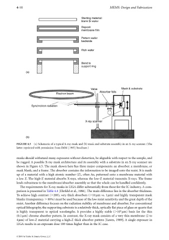
FIGURE 4.5 (a) Schematic of a typical X-ray mask and (b) mask and substrate assembly in an X-ray scanner. (The
latter reprinted with permission from IMM [1995] brochure.)
masks should withstand many exposures without distortion, be alignable with respect to the sample, and
be rugged. A possible X-ray mask architecture and its assembly with a substrate in an X-ray scanner are
shown in Figure 4.5. The mask shown here has three major components: an absorber; a membrane, or
mask blank; and a frame. The absorber contains the information to be imaged onto the resist. It is made
up of a material with a high atomic number (Z), often Au, patterned onto a membrane material with
a low Z. The high-Z material absorbs X-rays, whereas the low-Z material transmits X-rays. The frame
lends robustness to the membrane/absorber assembly so that the whole can be handled confidently.
The requirements for X-ray masks in LIGA differ substantially from those for the IC industry. A com-
parison is presented in Table 4.4 [Ehrfeld et al., 1986]. The main difference lies in the absorber thickness.
To achieve high contrast ( 200), very thick absorbers ( 10 µm vs. 1µm) and highly transparent mask
blanks (transparency 80%) must be used because of the low resist sensitivity and the great depth of the
resist. Another difference focuses on the radiation stability of membrane and absorber. For conventional
optical lithography, the supporting substrate is a relatively thick, optically flat piece of glass or quartz that
6
is highly transparent to optical wavelengths. It provides a highly stable ( 10 µm) basis for the thin
(0.1µm) chrome absorber pattern. In contrast, the X-ray mask consists of a very thin membrane (2 to
4µm) of low-Z material carrying a high-Z thick absorber pattern [Lawes, 1989]. A single exposure in
LIGA results in an exposure dose 100 times higher than in the IC case.
© 2006 by Taylor & Francis Group, LLC