
Page 266 -
P. 266
LIGA and Micromolding 4-7
H
Electron orbit
Acceleration
(i ) P
= Radius of orbit
H = Magnetic field
i = Circulating current
R
2
mc
Angle ≈
E
Mask-wafer combination mechanically
moved through sheet of X-radiation
X-rays
Inset:
Clearance Clearance E
variable variable
Doctor blade
D C
B
P
Liquid
resist
Clearance
Film flow
variable
D: Doctoring roll (metal or rubber)
P: Pumping roll (metal or rubber)
C: Coating roll (metal or rubber)
B: Back roll (rubber)
E: Exposure roll (metal)
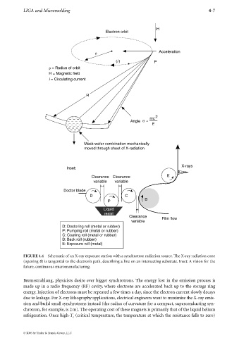
FIGURE 4.4 Schematic of an X-ray exposure station with a synchrotron radiation source. The X-ray radiation cone
(opening θ) is tangential to the electron’s path, describing a line on an intersecting substrate. Inset: A vision for the
future, continuous micromanufacturing.
Bremsstrahlung, physicists desire ever bigger synchrotrons. The energy lost in the emission process is
made up in a radio frequency (RF) cavity, where electrons are accelerated back up to the storage ring
energy. Injection of electrons must be repeated a few times a day, since the electron current slowly decays
due to leakage. For X-ray lithography applications, electrical engineers want to maximize the X-ray emis-
sion and build small synchrotrons instead (the radius of curvature for a compact, superconducting syn-
chrotron, for example, is 2m). The operating cost of these magnets is primarily that of the liquid helium
refrigeration. Once high-T (critical temperature, the temperature at which the resistance falls to zero)
c
© 2006 by Taylor & Francis Group, LLC