
Page 489 -
P. 489
50
40
30
20
10
0
−10
40
30 40
20 30
20
10 10
0 0
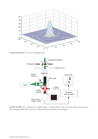
COLOR FIGURE 10.2 PIV cross-correlation peak.
Fluorescent particles
Focal plane
Device cover
Objective
Exciter Vector plot
532 nm
Filter cube
Laser
Emitter
610 nm
Beam
expander Computer
(post process)
CCD camera
(1280 × 1024)
COLOR FIGURE 10.3 Schematic of a µPIV system. A pulsed Nd:YAG laser is used to illuminate fluorescent
flow-tracing particles, and a cooled CCD camera is used to record the particle images.
© 2006 by Taylor & Francis Group, LLC