
Page 202 - Make Your Own PCBs with EAGLE from Schematic Designs to Finished Boards
P. 202
Turning our attention to the more minor components, there is going to be an NPN transistor for
each of the cathodes of the four digits and accompanying base resistors. There will also be current-
limitting resistors for each of the eight anodes, as well as the apostrophy and colon anodes.
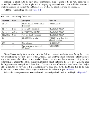
Add the components as listed in Table 8-2.
TABLE 8-2 Remaining Components
You will need to flip the transistors using the Mirror command so that they are facing the correct
way around for the base to be closer to the Arduino. I also used the Smash command on the transistors
to put the Name label closer to the symbol. Rather than add the four transistors using the Add
command, it is quicker to add one transistor, mirror it, smash and move the label closer, and then use
the Copy command to duplicate it three times. The same is true of the resistors of each value. So just
add one resistor, set its value to 1 kΩ, and then copy it three times for R1 to R4, and then do the same
for the other resistor values. Also change the values of the resistors as per Table 8-2.
When all the components are on the schematic, the design should look something like Figure 8-3.