
Page 207 - Make Your Own PCBs with EAGLE from Schematic Designs to Finished Boards
P. 207
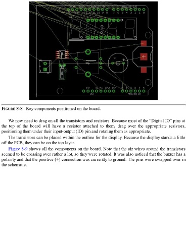
FIGURE 8-8   Key components positioned on the board.


      We now need to drag on all the transistors and resistors. Because most of the “Digital IO” pins at
  the  top  of  the  board  will  have  a  resistor  attached  to  them,  drag  over  the  appropriate  resistors,
  positioning them under their input-output (IO) pin and rotating them as appropriate.

      The transistors can be placed within the outline for the display. Because the display stands a little
  off the PCB, they can be on the top layer.
      Figure 8-9 shows all the components on the board. Note that the air wires around the transistors
  seemed to be crossing over rather a lot, so they were rotated. It was also noticed that the buzzer has a
  polarity and that the positive (+) connection was currently to ground. The pins were swapped over in

  the schematic.