
Page 204 - Make Your Own PCBs with EAGLE from Schematic Designs to Finished Boards
P. 204
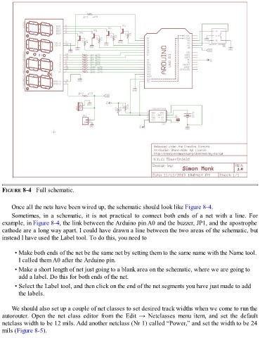
FIGURE 8-4   Full schematic.


      Once all the nets have been wired up, the schematic should look like Figure 8-4.
      Sometimes,  in  a  schematic,  it  is  not  practical  to  connect  both  ends  of  a  net  with  a  line.  For

  example, in Figure 8-4, the link between the Arduino pin A0 and the buzzer, JP1, and the apostrophe
  cathode are a long way apart. I could have drawn a line between the two areas of the schematic, but
  instead I have used the Label tool. To do this, you need to


        • Make both ends of the net be the same net by setting them to the same name with the Name tool.

          I called them A0 after the Arduino pin.
        • Make a short length of net just going to a blank area on the schematic, where we are going to
          add a label. Do this for both ends of the net.

        • Select the Label tool, and then click on the end of the net segments you have just made to add
          the labels.


      We should also set up a couple of net classes to set desired track widths when we come to run the
  autorouter.  Open  the  net  class  editor  from  the  Edit  →  Netclasses  menu  item,  and  set  the  default
  netclass width to be 12 mils. Add another netclass (Nr 1) called “Power,” and set the width to be 24
  mils (Figure 8-5).