
Page 208 - Make Your Own PCBs with EAGLE from Schematic Designs to Finished Boards
P. 208
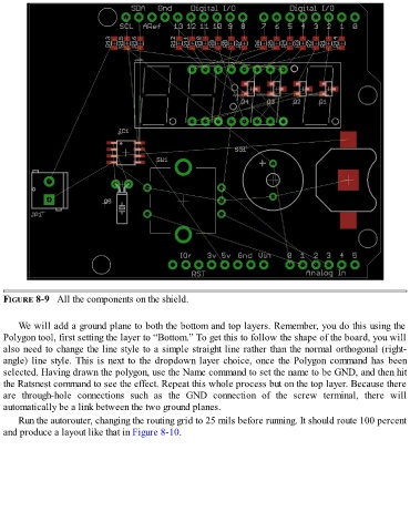
FIGURE 8-9   All the components on the shield.


      We will add a ground plane to both the bottom and top layers. Remember, you do this using the
  Polygon tool, first setting the layer to “Bottom.” To get this to follow the shape of the board, you will
  also need to change the line style to a simple straight line rather than the normal orthogonal (right-
  angle) line style. This is next to the dropdown layer choice, once the Polygon command has been
  selected. Having drawn the polygon, use the Name command to set the name to be GND, and then hit

  the Ratsnest command to see the effect. Repeat this whole process but on the top layer. Because there
  are  through-hole  connections  such  as  the  GND  connection  of  the  screw  terminal,  there  will
  automatically be a link between the two ground planes.

      Run the autorouter, changing the routing grid to 25 mils before running. It should route 100 percent
  and produce a layout like that in Figure 8-10.