
Page 205 - Make Your Own PCBs with EAGLE from Schematic Designs to Finished Boards
P. 205
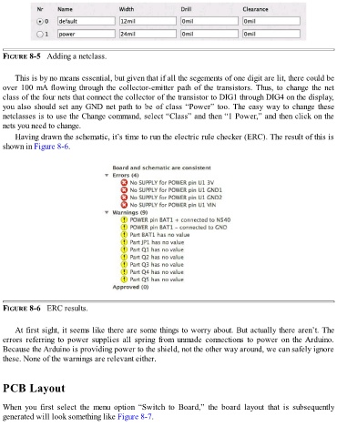
FIGURE 8-5   Adding a netclass.


      This is by no means essential, but given that if all the segements of one digit are lit, there could be
  over 100 mA flowing through the collector-emitter path of the transistors. Thus, to change the net
  class of the four nets that connect the collector of the transistor to DIG1 through DIG4 on the display,

  you also should set any GND net path to be of class “Power” too. The easy way to change these
  netclasses is to use the Change command, select “Class” and then “1 Power,” and then click on the
  nets you need to change.
      Having drawn the schematic, it’s time to run the electric rule checker (ERC). The result of this is
  shown in Figure 8-6.


  FIGURE 8-6   ERC results.


      At first sight, it seems like there are some things to worry about. But actually there aren’t. The
  errors  referring  to  power  supplies  all  spring  from  unmade  connections  to  power  on  the Arduino.
  Because the Arduino is providing power to the shield, not the other way around, we can safely ignore
  these. None of the warnings are relevant either.


  PCB Layout


  When  you  first  select  the  menu  option  “Switch  to  Board,”  the  board  layout  that  is  subsequently
  generated will look something like Figure 8-7.