
Page 206 - Make Your Own PCBs with EAGLE from Schematic Designs to Finished Boards
P. 206
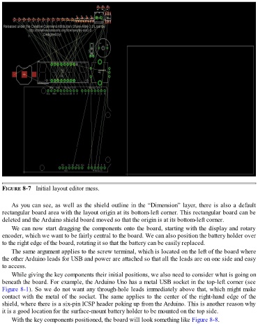
FIGURE 8-7   Initial layout editor mess.


      As you can see, as well as the shield outline in the “Dimension” layer, there is also a default
  rectangular board area with the layout origin at its bottom-left corner. This rectangular board can be
  deleted and the Arduino shield board moved so that the origin is at its bottom-left corner.

      We can now start dragging the components onto the board, starting with the display and rotary
  encoder, which we want to be fairly central to the board. We can also position the battery holder over
  to the right edge of the board, rotating it so that the battery can be easily replaced.

      The same argument applies to the screw terminal, which is located on the left of the board where
  the other Arduino leads for USB and power are attached so that all the leads are on one side and easy
  to access.
      While giving the key components their initial positions, we also need to consider what is going on

  beneath the board. For example, the Arduino Uno has a metal USB socket in the top-left corner (see
  Figure 8-1). So we do not want any through-hole leads immediately above that, which might make
  contact with the metal of the socket. The same applies to the center of the right-hand edge of the
  shield, where there is a six-pin ICSP header poking up from the Arduino. This is another reason why
  it is a good location for the surface-mount battery holder to be mounted on the top side.

      With the key components positioned, the board will look something like Figure 8-8.