
Page 203 - Make Your Own PCBs with EAGLE from Schematic Designs to Finished Boards
P. 203
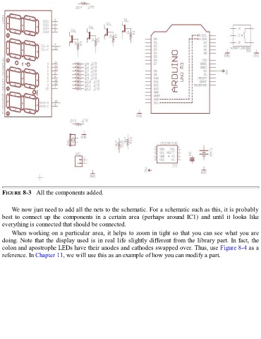
FIGURE 8-3   All the components added.


      We now just need to add all the nets to the schematic. For a schematic such as this, it is probably

  best  to  connect  up  the  components  in  a  certain  area  (perhaps  around  IC1)  and  until  it  looks  like
  everything is connected that should be connected.
      When working on a particular area, it helps to zoom in tight so that you can see what you are

  doing. Note that the display used is in real life slightly different from the library part. In fact, the
  colon and apostrophe LEDs have their anodes and cathodes swapped over. Thus, use Figure 8-4 as a
  reference. In Chapter 11, we will use this as an example of how you can modify a part.