
Page 478 - 04. Subyek Engineering Materials - Manufacturing, Engineering and Technology SI 6th Edition - Serope Kalpakjian, Stephen Schmid (2009)
P. 478
Chapter 17 Powder-Metal Processing and Equipment
Poor Good
oooooo QT P G d
E al? E OO F
Finer radius
F
.
cor
Fillet radius
Sharp radius
e oo . .
Sharp radius
ii
ii
Sharp can be
Must be
(H) sa t. (D) radius
B
Fillet
5
s
ra ius sr F?
punch Die _,1 Sharp radius er-§=>§
0.25 mm
(min)
Upper
Fillet
Feather edge
radius
té 5
required on
s as
E é
Workpiece punch (C) .r id) §§ .
-ef
Acceptable Best Acceptable with additional operations
Die Punch 0-25_mm -4 -
ee
(min) /§eo°-45°
workpiece W Hole must Thread must be
be drilled machined
(9) (f)
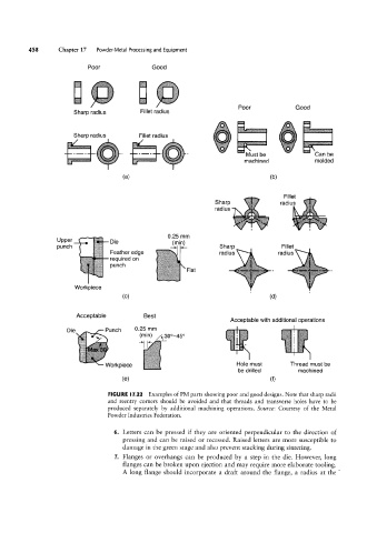
FIGURE l7.22 Examples of PM parts showing poor and good designs. Note that sharp radii
and reentry corners should be avoided and that threads and transverse holes have to be
produced separately by additional machining operations. Source: Courtesy of the Metal
Powder Industries Federation.
6. Letters can be pressed if they are oriented perpendicular to the direction of
pressing and can be raised or recessed. Raised letters are more susceptible to
damage in the green stage and also prevent stacking during sintering.
7. Flanges or overhangs can be produced by a step in the die. However, long
flanges can be broken upon ejection and may require more elaborate tooling.
A long flange should incorporate a draft around the flange, a radius at the