
Page 477 - 04. Subyek Engineering Materials - Manufacturing, Engineering and Technology SI 6th Edition - Serope Kalpakjian, Stephen Schmid (2009)
P. 477
Section 17.6 Design Considerations 457
and tensile strength of the part are improved and the pores are filled, thus pre-
venting moisture penetration (which could cause corrosion). Furthermore,
since some porosity is desirable when an infiltrant is used, the part may be sin-
tered only partially, resulting in lower thermal warpage.
6. Electroplating (Section 34.9) can be applied on PM parts, but special care is re-
quired to remove the electrolytic fluid, since it presents health hazards. Under
some conditions, electroplating can seal a part and eliminate its permeability.
I7.6 Design Considerations
Because of the unique properties of metal powders, their flow characteristics in the
die, and the brittleness of green compacts, there are certain design principles that
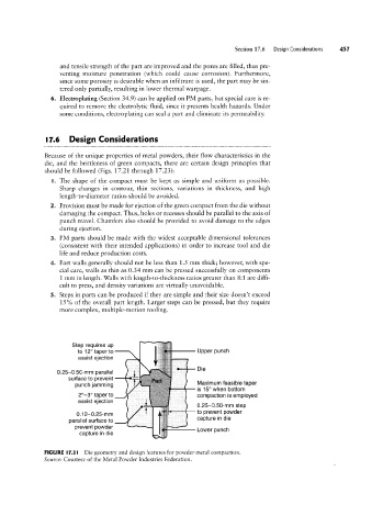
should be followed (Figs. 17.21 through 1723):
I. The shape of the compact must be kept as simple and uniform as possible.
Sharp changes in contour, thin sections, variations in thickness, and high
length-to-diameter ratios should be avoided.
2. Provision must be made for ejection of the green compact from the die without
damaging the compact. Thus, holes or recesses should be parallel to the axis of
punch travel. Chamfers also should be provided to avoid damage to the edges
during ejection.
3. PM parts should be made with the widest acceptable dimensional tolerances
(consistent with their intended applications) in order to increase tool and die
life and reduce production costs.
4. Part walls generally should not be less than 1.5 mm thick; however, with spe-
cial care, walls as thin as 0.34 mm can be pressed successfully on components
1 mm in length. Walls with length-to-thickness ratios greater than 8:1 are diffi-
cult to press, and density variations are virtually unavoidable.
5. Steps in parts can be produced if they are simple and their size doesn’t exceed
15% of the overall part length. Larger steps can be pressed, but they require
assist ejection
more complex, multiple-motion tooling.
to 12° taper to
0.25-0.50-mm parallel .u Upper punch
Step requires up
Surface to prevent
,.,.....,.
.y
yy
Die
*P
punch jamming 1 Maximum feasible taper
,", 7, f
cily
is 15° when bottom
0.12-0.25-mm lyri *F compaction is employed
2°-3° taper to
be
yltr
assist ejection ‘ if
0.25-0.50-mm step
capture in die
parallel surface to * = if to prevent powder
prevent powder W Lower punch
capture in die if
iiiii
FIGURE |1.2l Die geometry and design features for powder-metal compaction.
Source: Courtesy of the Metal Powder Industries Federation.