
Page 513 - 04. Subyek Engineering Materials - Manufacturing, Engineering and Technology SI 6th Edition - Serope Kalpakjian, Stephen Schmid (2009)
P. 513
Section 19. 3 Injection Molding 493
that can significantly increase the tensile strength of the fibers. In addition, the
liquid crystals are aligned along the fiber axis by the strain encountered during
extrusion. The filaments emerge from the spinneret with an unusually high de-
gree of orientation relative to each other-further enhancing their strength.
This process also is called dry-ir/et spinning, because the filaments first pass
through air and then are cooled further in a liquid bath. Some high-strength
polyethylene and aramid fibers are produced by gel spinning.
A necessary step in the production of most fibers is the application of signifi-
cant stretching to induce orientation of the polymer molecules in the fiber direction.
This orientation is the main reason for the high strength of the fibers, compared
with the polymer in bulk form. The stretching can be done While the polymer is still
pliable-just after extrusion from the spinneret-or it can be performed as a cold-
drawing operation. The strain induced can be as high as 800%.
Graphite fibers are produced from different polymer fibers by pyrolysis. In this
operation, controlled heat in the range from 1500° to 3000°C is applied to the poly-
mer fiber (typically polyacrylonitrile, PAN) to drive off all elements except the car-
bon. The fiber is under tension in order to develop a high degree of orientation in the
resulting fiber structure. (See also Section 9.2.1 on the properties of graphite fibers
and other details.)
l9.3 Injection Molding
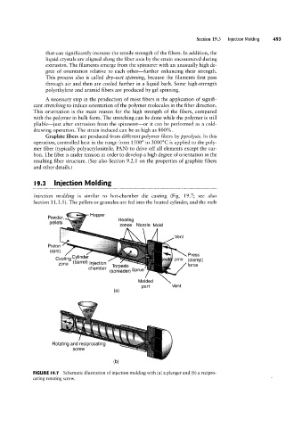
Injection molding is similar to hot-chamber die casting (Fig. 19.7, see also
Section 11.3.5 ). The pellets or granules are fed into the heated cylinder, and the melt
Powder Hopper
penets Heating
zones Nozzle Mold
\ /1
Vent
ress
Piston
(ram) \P
Cooiing ping (C|amp)
Torpedo
‘”a"e'>g,;1§;;§;,;Q
(spreader) Sprue /force
Molded
part Vent
(H)
Rotating and reciprocating
screw
FIGURE I9.1 Schematic illustration of injection molding with (a) a plunger and (b) a recipro-
cating rotating screw.