
Page 548 - 04. Subyek Engineering Materials - Manufacturing, Engineering and Technology SI 6th Edition - Serope Kalpakjian, Stephen Schmid (2009)
P. 548
528 Chapter 20 Rapid-Prototyping Processes and Operations
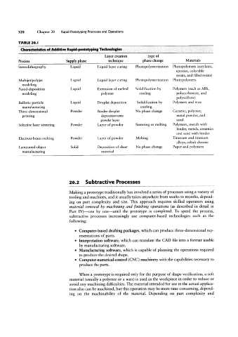
TABLE 20.l
Characteristics of Additive Rapid-prototyping Technologies
Layer creation Type of
Process Supply phase technique phase change Materials
Stereolithography Liquid Liquid layer curing Photopolymerization Photopolymers (acrylates,
epoxies, colorable
resins, and filled resins)
Multijet/polyjet Liquid Liquid layer curing Photopolymerization Photopolymers
modeling
Fused-deposition Liquid Extrusion of melted Solidification by Polymers (such as ABS,
modeling polymer cooling polycarbonate, and
polysulfone)
Ballistic-particle Liquid Droplet deposition Solidification by Polymers and wax
manufacturing cooling
Three-dimensional Powder Binder-droplet No phase change Ceramic, polymer,
printing deposition onto metal powder, and
powder layer sand
Selective laser sintering Powder Layer of powder Sintering or melting Polymers, metals with
binder, metals, ceramics
and sand with binder
Electron-beam melting Powder Layer of powder Melting Titanium and titanium
alloys, cobalt chrome
Laminated-object Solid Deposition of sheet No phase change Paper and polymers
manufacturing material
20.2 Subtractive Processes
Making a prototype traditionally has involved a series of processes using a variety of
tooling and machines, and it usually takes anywhere from weeks to months, depend-
ing on part complexity and size. This approach requires skilled operators using
material removal by machining and Hnis/cling operations (as described in detail in
Part IV)-one by one-until the prototype is completed. To speed the process,
subtractive processes increasingly use computer-based technologies such as the
following:
° Computer-based drafting packages, which can produce three-dimensional rep-
resentations of parts.
° Interpretation software, which can translate the CAD file into a format usable
by manufacturing software.
° Manufacturing software, which is capable of planning the operations required
to produce the desired shape.
° Computer-numerical-control (CNC) machinery with the capabilities necessary to
produce the parts.
When a prototype is required only for the purpose of shape verification, a soft
material (usually a polymer or a wax) is used as the workpiece in order to reduce or
avoid any machining difficulties. The material intended for use in the actual applica-
tion also can be machined, but this operation may be more time consuming, depend-
ing on the machinability of the material. Depending on part complexity and