
Page 551 - 04. Subyek Engineering Materials - Manufacturing, Engineering and Technology SI 6th Edition - Serope Kalpakjian, Stephen Schmid (2009)
P. 551
Section 20.3 Additive Processes
é
fi
Side View
(H) (D)
'/2:
Model Model
yii Su ort \ \
'Q pp
Z ,&» ea /2
,~%v §§§!fé”' /‘
/
A Support
(C) (Cl)
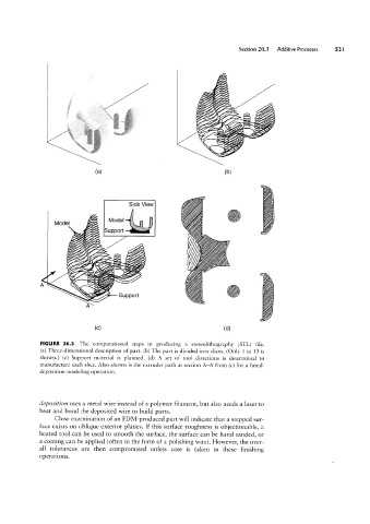
FIGURE 20.3 The computational steps in producing a stereolithography (STL) file.
(a) Three-dimensional description of part. (b) The part is divided into slices. (Only 1 in 10 is
shown.) (c) Support material is l p anne d. (d) A set of tool directions is determined to
manufacture each slice. Also shown is the extruder path at section A-A from (c) for a fused-
deposition-modeling operation.
deposition uses a metal Wire instead of a polymer filament, but also needs a laser to
heat and bond the deposited Wire to build parts.
Close examination of an FDM-produced part will indicate that a stepped sur-
face exists on oblique exterior planes. If this surface roughness is objectionable, a
heated tool can be used to smooth the surface, the surface can be hand sanded, or
a coating can be applied (often in the form of a polis h'mg Wax ). However, the over-
all tolerances are then compromise d unless care is taken in these finishing
operations.