
Page 550 - 04. Subyek Engineering Materials - Manufacturing, Engineering and Technology SI 6th Edition - Serope Kalpakjian, Stephen Schmid (2009)
P. 550
0 Chapter 20 Rapid-Prototyping Processes and Operations
20.3 Additive Processes
Additive rapid-prototyping operations all build parts in layers, and as summarized
in Table 20.1, they consist of stereolitliograpliy, Multiiet/polyiet modeling, fused-
deposition modeling, ballistic-particle manufacturing, three-dimensional printing,
selective laser sintering, electron-beam and laminated-object manufacturing. In
order to visualize the methodology used, it is beneficial to think of constructing a
loaf of bread by stacking and bonding individual slices on top of each other. All of
the processes described in this section build parts slice by slice. The main difference
between the various additive processes lies in the method of producing the individ-
ual slices, which are typically 0.1 to 0.5 mm thick and can be thicker for some
systems.
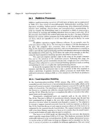
All additive operations require elaborate software. As an example, note the
solid part shown in Fig. 20.3a. The first step is to obtain a CAD file description of
the part. The computer then constructs slices of the three-dimensional part
(Fig. 20.3b). Each slice is analyzed separately, and a set of instructions is compiled in
order to provide the rapid-prototyping machine with detailed information regarding
the manufacture of the part. Fig. 20.3d shows the paths of the extruder in one slice,
using the fused-deposition-modeling operation described in Section 20.3.1.
This approach requires operator input in the setup of the proper computer
files and in the initiation of the production process. Following that stage, the
machines generally operate unattended and provide a rough part after a few hours.
The part is then subjected to a series of manual finishing operations (such as sanding
and painting) in order to complete the rapid-prototyping process.
It should be recognized that the setup and finishing operations are very labor
intensive and that the production time is only a portion of the time required to
obtain a prototype. In general, however, additive processes are much faster than
subtractive processes, taking as little as a few minutes to a few hours to produce a
part.
20.3.l Fused-deposition Modeling
In the fused-deposition-modeling (FDM) process (Fig. 20.4), a gantry robot-
controlled extruder head moves in two principal directions over a table, which can be
raised and lowered as needed. A thermoplastic filament is extruded through the small
orifice of a heated die. The initial layer is placed on a foam foundation by extruding
the filament at a constant rate while the extruder head follows a predetermined path
(see Fig. 20.3d). When the first layer is completed, the table is lowered so that subse-
quent layers can be superimposed.
Occasionally, complicated parts are required, such as the one shown in
Fig. 20.5a. This part is difficult to manufacture directly, because once the part has
been constructed up to height a, the next slice would require the filament to be
placed in a location where no material exists beneath to support it. The solution is
to extrude a support material separately from the modeling material, as shown in
Fig. 20.5 b. Note that the use of such support structures allows all of the layers to be
supported by the material directly beneath them. The support material is produced
with a less dense filament spacing on a layer, so it is weaker than the model materi-
al and can be broken off easily after the part is completed.
The layers in an FDM model are determined by the extrusion-die diameter,
which typically ranges from 0.050 to 0.12 mm. This thickness represents the best
achievable tolerance in the vertical direction. In the x-y plane, dimensional accura-
cy can be as fine as 0.025 mm-as long as a filament can be extruded into the fea-
ture. A variety of polymers are available for different applications. Flat wire metal