
Page 553 - 04. Subyek Engineering Materials - Manufacturing, Engineering and Technology SI 6th Edition - Serope Kalpakjian, Stephen Schmid (2009)
P. 553
Section 20.3 Additive Processes 533
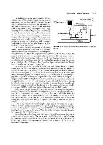
At its highest position (depth a in Fig. 20.6), a
Platform motion
shallow layer of liquid exists above the platform. A
laser generating an ultraviolet (UV) beam is focused UV light source
upon a selected surface area of the photopolymer UV curable
liquid
and then moved around in the x-y plane. The beam \ I’
Liquid
cures that portion of the photopolymer (say, a ring- x ; surface
shaped portion) and thereby produces a solid body. V
The platform is then lowered sufficiently to cover 3 c
Formed part
the cured polymer with another layer of liquid poly- "b Vat
mer, and the sequence is repeated. The process is re- | |
peated until level b in Fig. 20.6 is reached. Thus far,
we have generated a cylindrical part with a constant Platform
wall thickness. Note that the platform is now low-
ered by a vertical distance ab.
FIGURE 20.6 Schematic illustration of the stereolithography
At level b, the x-y movements of the beam
process.
define a wider geometry, so we now have a flange-
shaped portion that is being produced over the previ-
ously formed part. After the proper thickness of the liquid has been cured, the
process is repeated, producing another cylindrical section between levels I9 and c.
Note that the surrounding liquid polymer is still fluid (because it has not been ex-
posed to the ultraviolet beam) and that the part has been produced from the bottom
up in individual “slices.” The unused portion of the liquid polymer can be used again
to make another part or another prototype.
Note that the term “stereolithography,” as used to describe this process,
comes from the facts that the movements are three-dimensional and the process is
similar to lithography (see Section 28.7), in which the image to be printed on a flat
surface is ink receptive and the blank areas are ink repellent. Note also that, like
FDM, stereolithography can utilize a weaker support material. In stereolithogra-
phy, this support takes the form of perforated structures. After its completion,
the part is removed from the platform, blotted, and cleaned ultrasonically and with
an alcohol bath. Then the support structure is removed, and the part is subjected
to a final curing cycle in an oven. The smallest tolerance that can be achieved
in stereolithography depends on the sharpness of the focus of the laser; typically,
it is around 0.0125 mm. Oblique surfaces also can be of very high quality.
Solid parts can be produced by applying special laser-scanning patterns to
speed up production. For example, by spacing scan lines in stereolithography, vol-
umes or pockets of uncured polymer can be formed within cured shells. When the
part is later placed in a postprocessing oven, the pockets cure and a solid
part forms. Similarly, parts that are to be investment cast will have a drainable
honeycomb structure which permits a significant fraction of the part to remain
uncured.
Total cycle times in stereolithography range from a few hours to a day-
without postprocessing such as sanding and painting. Depending on their capacity,
the cost of the machines is in the range from $100,000 to $400,000. The cost ofthe
liquid polymer is on the order from $80 per litre. The maximum part size that can
be produced is 0.5 >< 0.5 >< 0.6 m..
Stereolithography has been used with highly focused lasers to produce parts
with micrometer-sized features. The use of optics required to produce such features
necessitates thinner layers and lower volumetric cure rates. When stereolithography
is used to fabricate micromechanical systems (see Chapter 29), it is called
microstereolithography.