
Page 556 - 04. Subyek Engineering Materials - Manufacturing, Engineering and Technology SI 6th Edition - Serope Kalpakjian, Stephen Schmid (2009)
P. 556
Chapter 20 Rapid-Prototyping Processes and Operations
from an energy standpoint (compared with 10-20% efficiency for selective laser
sintering), so that the titanium powder is actually melted and fully dense parts can
be produced. A volume build rate of up to 60 cm3/hr can be obtained, with individ-
ual layer thicknesses of 0.05 0-0.200 mm. Hot isostatic pressing (Section 17.3.2)
also can be performed on parts to improve their fatigue strength. Although applied
mainly to titanium and cobalt-chrome to date, the process is being developed for
stainless steels, aluminum, and copper alloys.
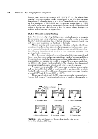
20.3.6 Three-dimensional Printing
In the three-dimensional-printing (3DP) process, a printhead deposits an inorganic
binder material onto a layer of polymer, ceramic, or metallic powder, as shown in
Fig. 20.9. A piston supporting the powder bed is lowered incrementally, and with
each step, a layer is deposited and then fused by the binder.
Multijet modeling and polyjet processes (described in Section 2O.3.3) are
sometimes referred to as three-dimensional printing approaches, because they oper-
ate in a similar fashion to ink-jet printers but incorporate a third (thickness) direc-
tion. However, three-dimensional printing is most commonly associated with
printing a binder onto powder.
Three-dimensional printing allows considerable flexibility in the materials and
binders used. Commonly used powder materials are blends of polymers and fibers,
foundry sand, and metals. Furthermore, since multiple binder printheads can be in-
corporated into one machine, it is possible to produce full-color prototypes by hav-
ing different-color binders (see Example 20.3). The effect is a three-dimensional
Eli*
analog to printing photographs using three ink colors on an ink-jet printer.
A common part produced by 3DP from ceramic powder is a ceramic-casting
shell (see Section 11.2.4), in which an aluminum-oxide or aluminum-silica powder is
fused with a silica binder. The molds have to be postprocessed in two steps: (1) curing
at around 150°C and (2) firing at 1000° to 1500°C.
The parts produced through the 3DP process are somewhat porous and there-
fore may lack strength. Three-dimensional printing of metal powders can also be
_;;fi¢==
|_* Holler mechanism |1>
,/-Powder Binder
ET” Elle ~;;2;;;,,.
I!!
if
1. Spread powder 2. Print layer 3. Piston movement
A..
4. Intermediate stage 5. Last layer printed 6. Finished part
FIGURE 20.9 Schematic illustration of the three-dimensional-printing process.
Source: After E. Sachs and M. Cima.