
Page 171 - Marks Calculation for Machine Design
P. 171
P1: Shibu
January 4, 2005
14:25
Brown.cls
Brown˙C04
CHAPTER 4
COMBINED LOADINGS
4.1 INTRODUCTION
Combined loadings on machine elements are a combination of two or more of the fundamen-
tal and advanced loadings discussed in Chaps. 1 and 3. This includes axial loading, direct
shear loading, torsion, bending, pressure loading inside thin-walled vessels and thick-walled
cylinders, and press or shrink fits, contact loading between either spheres or cylinders, and
rotational loading on thin circular disks. In actual practice, it is difficult to have more than
two of these loadings acting at the same time. So in this chapter, only the most common
combinations will be presented.
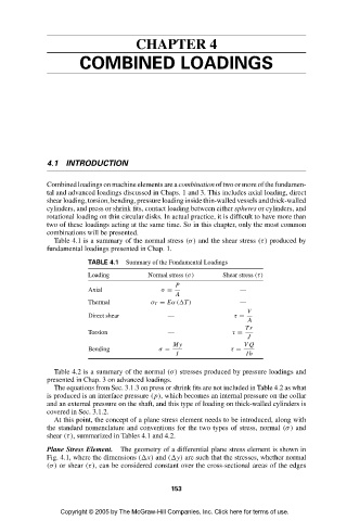
Table 4.1 is a summary of the normal stress (σ) and the shear stress (τ) produced by
fundamental loadings presented in Chap. 1.
TABLE 4.1 Summary of the Fundamental Loadings
Loading Normal stress (σ) Shear stress (τ)
P
Axial σ = —
A
Thermal σ T = Eα( T ) —
V
Direct shear — τ =
A
Tr
Torsion — τ =
J
My VQ
Bending σ = τ =
I Ib
Table 4.2 is a summary of the normal (σ) stresses produced by pressure loadings and
presented in Chap. 3 on advanced loadings.
The equations from Sec. 3.1.3 on press or shrink fits are not included in Table 4.2 as what
is produced is an interface pressure (p), which becomes an internal pressure on the collar
and an external pressure on the shaft, and this type of loading on thick-walled cylinders is
covered in Sec. 3.1.2.
At this point, the concept of a plane stress element needs to be introduced, along with
the standard nomenclature and conventions for the two types of stress, normal (σ) and
shear (τ), summarized in Tables 4.1 and 4.2.
Plane Stress Element. The geometry of a differential plane stress element is shown in
Fig. 4.1, where the dimensions ( x) and ( y) are such that the stresses, whether normal
(σ) or shear (τ), can be considered constant over the cross-sectional areas of the edges
153
Copyright © 2005 by The McGraw-Hill Companies, Inc. Click here for terms of use.