
Page 175 - Marks Calculation for Machine Design
P. 175
P1: Shibu
14:25
January 4, 2005
Brown.cls
Brown˙C04
s
yy
t xy COMBINED LOADINGS t xy 0 157
t
t xy xy
P
s xx s xx s = A
xx
Æ
s xx
Tr
t xy t =
xy
J
t xy t xy
0
s yy
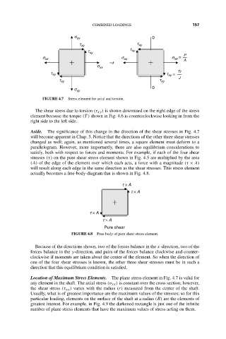
FIGURE 4.7 Stress element for axial and torsion.
The shear stress due to torsion (τ xy ) is shown downward on the right edge of the stress
element because the torque (T ) shown in Fig. 4.6 is counterclockwise looking in from the
right side to the left side.
Aside. The significance of this change in the direction of the shear stresses in Fig. 4.7
will become apparent in Chap. 5. Notice that the directions of the other three shear stresses
changed as well; again, as mentioned several times, a square element must deform to a
parallelogram. However, more importantly, there are also equilibrium considerations to
satisfy, both with respect to forces and moments. For example, if each of the four shear
stresses (τ) on the pure shear stress element shown in Fig. 4.5 are multiplied by the area
(A) of the edge of the element over which each acts, a force with a magnitude (τ × A)
will result along each edge in the same direction as the shear stresses. This stress element
actually becomes a free-body-diagram that is shown in Fig. 4.8.
t × A
t × A
t × A
t × A
Pure shear
FIGURE 4.8 Free-body of pure shear stress element.
Because of the directions shown, two of the forces balance in the x-direction, two of the
forces balance in the y-direction, and pairs of the forces balance clockwise and counter-
clockwise if moments are taken about the center of the element. So when the direction of
one of the four shear stresses is known, the other three shear stresses must be in such a
direction that this equilibrium condition is satisfied.
Location of Maximum Stress Elements. The plane stress element in Fig. 4.7 is valid for
any element in the shaft. The axial stress (σ xx ) is constant over the cross section; however,
the shear stress (τ xy ) varies with the radius (r) measured from the center of the shaft.
Usually, what is of greatest importance are the maximum values of the stresses; so for this
particular loading, elements on the surface of the shaft at a radius (R) are the elements of
greatest interest. For example, in Fig. 4.9 the darkened rectangle is just one of the infinite
number of plane stress elements that have the maximum values of stress acting on them.