
Page 176 - Marks Calculation for Machine Design
P. 176
P1: Shibu
January 4, 2005
14:25
Brown.cls
Brown˙C04
158
STRENGTH OF MACHINES
Stress element T
R
r = 0
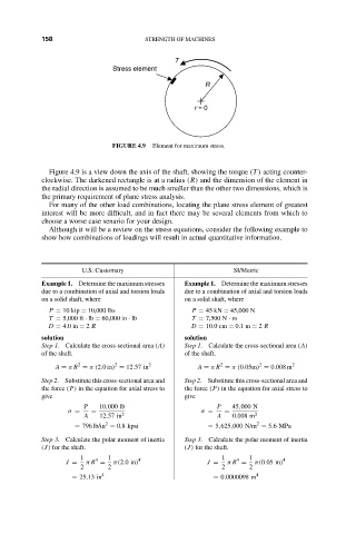
FIGURE 4.9 Element for maximum stress.
Figure 4.9 is a view down the axis of the shaft, showing the torque (T ) acting counter-
clockwise. The darkened rectangle is at a radius (R) and the dimension of the element in
the radial direction is assumed to be much smaller than the other two dimensions, which is
the primary requirement of plane stress analysis.
For many of the other load combinations, locating the plane stress element of greatest
interest will be more difficult, and in fact there may be several elements from which to
choose a worse case senario for your design.
Although it will be a review on the stress equations, consider the following example to
show how combinations of loadings will result in actual quantitative information.
U.S. Customary SI/Metric
Example 1. Determine the maximum stresses Example 1. Determine the maximum stresses
due to a combination of axial and torsion loads due to a combination of axial and torsion loads
on a solid shaft, where on a solid shaft, where
P = 10 kip = 10,000 lbs P = 45 kN = 45,000 N
T = 5,000 ft · lb = 60,000 in · lb T = 7,500 N · m
D = 4.0 in = 2 R D = 10.0 cm = 0.1 m = 2 R
solution solution
Step 1. Calculate the cross-sectional area (A) Step 1. Calculate the cross-sectional area (A)
of the shaft. of the shaft.
2
2
2
2
A = π R = π(2.0in) = 12.57 in 2 A = π R = π(0.05m) = 0.008 m 2
Step 2. Substitute this cross-sectional area and Step 2. Substitute this cross-sectional area and
the force (P) in the equation for axial stress to the force (P) in the equation for axial stress to
give give
P 10,000 lb P 45,000 N
σ = = σ = =
A 12.57 in 2 A 0.008 m 2
2
2
= 796 lb/in = 0.8 kpsi = 5,625,000 N/m = 5.6MPa
Step 3. Calculate the polar moment of inertia Step 3. Calculate the polar moment of inertia
(J) for the shaft. (J) for the shaft.
1 4 1 4 1 4 1 4
J = π R = π(2.0in) J = π R = π(0.05 m)
2 2 2 2
= 25.13 in 4 = 0.0000098 m 4