
Page 177 - Marks Calculation for Machine Design
P. 177
P1: Shibu
14:25
January 4, 2005
Brown.cls
Brown˙C04
U.S. Customary COMBINED LOADINGS SI/Metric 159
Step 4. Substitute this polar moment of Step 4. Substitute this polar moment of
inertia (J), the radius (R), and the torque (T ) inertia (J), the radius (R), and the torque (T )
in the equation for maximum shear stress due in the equation for maximum shear stress due
to torsion to give to torsion to give
TR (60,000 in · lb)(2.0in) TR (7,500 N · m)(0.05 m)
τ max = = 4 τ max = = 4
J 25.13 in J 0.0000098 m
2
2
= 4,775 lb/in = 4.8 kpsi = 38,270,000 N/m = 38.3MPa
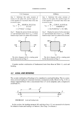
Step 5. Display the answers for the axial stress Step 5. Display the answers for the axial stress
(σ) and maximum shear stress (τ max ), in kpsi, (σ) and maximum shear stress (τ max ),inMPa,
found in steps 2 and 4 on a plane stress element. found in steps 2 and 4 on a plane stress element.
0 0
4.8 38.3
0.8 0.8 5.6 5.6
4.8 38.3
0 0
The above diagram will be a starting point The above diagram will be a starting point
for the discussions in Chap. 5. for the discussions in Chap. 5.
Consider another combination of fundamental loads from those in Table 4.1, axial and
bending.
4.3 AXIAL AND BENDING
The second combination of loadings to be considered is axial and bending. This is a some-
what common loading for structural elements constrained axially. Shown in Fig. 4.10 is a
simply-supported beam with a concentrated force (F) at its midpoint, and a compressive
axial load (P).
F
L/2
P P
A B
L
FIGURE 4.10 Axial and bending loads.
In this section, the bending moment (M) and shear force (V ) are assumed to be known
for whatever beam and loading is of interest. (See Chap. 2 on Beams.)