
Page 182 - Marks Calculation for Machine Design
P. 182
P1: Shibu
January 4, 2005
Brown˙C04
Brown.cls
164
U.S. Customary 14:25 STRENGTH OF MACHINES SI/Metric
Step 6. Display the answers for the maximum Step 6. Display the answers for the maximum
normal compressive stress (σ xx ) found in step normal compressive stress (σ xx ) found in step
2 and the maximum shear stress (τ xy ) found in 2 and the maximum shear stress (τ xy ) found in
step 5, in kpsi, on a general stress element as step 5, in kpsi, on a general stress element as
0 0
2.5 4.5
0.25 0.25 1.2 1.2
2.5 4.5
0 0
Remember, the directions of the stresses Remember, the directions of the stresses
account for positive or negative signs. Also, as account for positive or negative signs. Also, as
with the final diagrams of Examples 1 and 2, with the final diagrams of Examples 1 and 2,
this diagram will be a starting point for the dis- this diagram will be a starting point for the dis-
cussions in Chap. 5. cussions in Chap. 5.
4.4 AXIAL AND THERMAL
The third combination of loading to be considered is an axial load and a thermal load. This
type of loading can occur when a machine element is put under a tensile, or compressive,
preload during assembly in a factory environment, then subjected to an additional thermal
load either due to a temperature drop in the winter or a temperature rise in the summer.
Recall that if the machine element is not constrained, then under a temperature change the
element merely gets longer or shorter and no stress is developed.
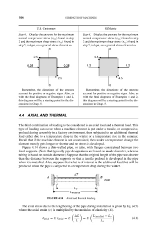
Figure 4.14 shows a thin-walled pipe, or tube, with flanges constrained between two
fixed supports. (Note that typically pipe designations are based on inside diameter, whereas
tubing is based on outside diameter.) Suppose that the original length of the pipe was shorter
than the distance between the supports so that a tensile preload is developed in the pipe
when it is installed. Also, suppose that what is of interest is the additional load that will be
produced when the pipe is subjected to a temperature drop during the winter.
∆T
A B
Axis
L o
L installed
FIGURE 4.14 Axial and thermal loading.
The axial stress due to the lengthening of the pipe during installation is given by Eq. (4.5)
where the axial strain (ε) is multiplied by the modulus of elasticity (E).
L L installed − L o
σ axial = E ε axial = E = E (4.1)
L L o