Page 187 - Marks Calculation for Machine Design
P. 187

P1: Shibu
                          January 4, 2005
                                      14:25
        Brown.cls
                 Brown˙C04
                                            COMBINED LOADINGS
                      Substituting for (r max = R) and the polar moment of inertia (J) in Eq. (4.9), the shear
                    stress (τ xy ) becomes the relationship given in Eq. (4.11).  169
                                            T AB r max  T AB R  2 T AB
                                       τ xy =      =  1    =    3               (4.11)
                                               J       πR  4  πR
                                                      2
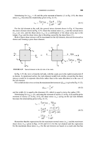
                      For the left element at the wall, the general stress element shown in Fig. 4.2 becomes
                    the stress element shown in Fig. 4.19, where the normal stress (σ xx ) and the normal stress
                    (σ yy ) are zero, and the shear stress (τ xy ) is a combination of the shear stress due to the
                    torque (T AB ) and the shear stress due to bending caused by the shear force (V ).
                      Both of these shear stresses will be maximum for the left element, directed downward as
                    shown and forming a pure shear element.
                                s yy                         0
                                   t xy                t xy
                                      t xy           t xy
                     s xx
                                             →     0                  0  Axis   B
                                        s xx
                       t xy                                            T r     VQ
                                                                   t  =   AB max  +  max
                                                                    xy
                           t xy                                 t xy      J     Ib
                                s yy                         0
                     FIGURE 4.19  Special element on the left side of the crank.

                      In Fig. 4.19, the view is from the left side, with the crank axis to the right toward point B
                    as shown. As mentioned earlier, the right element would look similar, except that the shear
                    stresses would be in opposite directions rather than in the same direction as is the case of
                    the left element.
                      Forasolidcircularcrosssection,themaximumfirstmoment(Q max )isgivenbyEq.(4.12),
                                                      2  3
                                               Q max =  R                       (4.12)
                                                      3
                    and the width (b) is equal to the diameter (D), which is equal to twice the radius (2R).
                      Substituting for (r max ), (b), and using the moment of inertia (I) in Eq. (4.8) and the polar
                    moment of inertia (J) in Eq. (4.9), the shear stress (τ xy ) acting on the left side element
                    becomes the relationship given in Eq. (4.13),
                                              T AB r max  VQ max
                                        τ xy =       +
                                                J        Ib
                                                            2  3
                                              T AB R  (V )  3  R
                                           =       +                            (4.13)
                                              1  πR 4  1  4
                                              2       4  πR  (2R)
                                              2 T AB  4 V
                                           =       +
                                              πR  3  3 πR 2
                      Remember that the expressions for the maximum normal stress (σ xx ) and the maximum
                    shear stress (τ xy ) given in Eqs. (4.10) and (4.11) for the top element and the expression
                    for the maximum shear stress (τ xy ) for the left element are based on a crank arm that has
   182   183   184   185   186   187   188   189   190   191   192