
Page 191 - Marks Calculation for Machine Design
P. 191
P1: Shibu
14:25
January 4, 2005
Brown.cls
Brown˙C04
COMBINED LOADINGS
173
distance between the supports so that a tensile preload is developed in the pipe when it is
installed. What is of interest is the maximum stress that the pipe will be subjected to by the
combination of the improper installation and the operational pressure.
As a review, the axial stress due to the lengthening of the pipe during installation is given
by Eq. (4.14), which is an application of Hooke’slaw,
L L installed − L o
σ axial = Eε axial = E = E (4.14)
L L o
where (E) is the modulus of elasticity of the pipe.
The internal pressure (p i ) produces two normal stresses in the wall of the pipe, an axial
stress (σ axial ) and a hoop stress (σ hoop ) given in Eqs. (4.15) and (4.16).
p i r m
σ axial = (4.15)
2 t
p i r m
σ hoop = (4.16)
t
where (r m ) is the mean radius (which can be assumed to be the inside radius) and (t) is the
wall thickness of the pipe. Notice that the hoop stress is twice the axial stress.
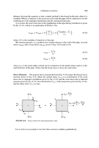
Stress Elements. The general stress element shown in Fig. 4.2 becomes the biaxial stress
element shown in Fig. 4.21, where the normal stress (σ xx ) is a combination of the axial
stress due to improper installation given by Eq. (4.14) and the axial stress due to internal
pressure given by Eq. (4.15), the normal stress (σ yy ) is the hoop stress given by Eq. (4.16),
and the shear stress (τ xy ) is zero.
p r
s yy s = i m
yy
t
t xy
0
t xy
∆L p r
i m
s xx s xx s = E +
xx
→ L 2t
s xx
t xy
0
t xy
s yy s yy
FIGURE 4.21 Stress element for axial and pressure loads.
Let us look at an example to see how these stresses combine quantitatively.