
Page 193 - Marks Calculation for Machine Design
P. 193
P1: Shibu
January 4, 2005
14:25
Brown.cls
Brown˙C04
U.S. Customary COMBINED LOADINGS SI/Metric 175
Step 5. Combine the axial stress (σ axial ) from Step 5. Combine the axial stress (σ axial ) from
step 2 and the axial stress (σ axial ) from step 3 to step 2 and the axial stress (σ axial ) from step 3 to
give the maximum stress (σ xx ) as give the maximum stress (σ xx ) as
σ xx = σ axial + σ axial σ xx = σ axial + σ axial
= (13.0 kpsi) + (0.5 kpsi) = (82.8MPa) + (3.5MPa)
= 13.5 kpsi = 86.3MPa
Step 6. Display the answers for the maximum Step 6. Display the answers for the maximum
stress (σ xx ) found in step 5, and the hoop stress stress (σ xx ) found in step 5 and the hoop stress
found in step 4, in kpsi, on the biaxial stress found in step 4, in MPa, on the biaxial stress
element of Fig. 4.21. element of Fig. 4.21.
1.0 7.0
0 0
13.5 13.5 86.3 86.3
0 0
1.0 7.0
The above diagram will be a starting point for The above diagram will be a starting point for
the discussions in Chap. 5. the discussions in Chap. 5.
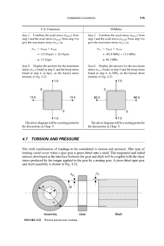
4.7 TORSION AND PRESSURE
The sixth combination of loadings to be considered is torsion and pressure. This type of
loading could occur when a spur gear is press fitted onto a shaft. The tangential and radial
stresses developed at the interface between the gear and shaft will be coupled with the shear
stress produced by the torque applied to the gear by a mating gear. A press fitted spur gear
and shaft assembly is shown in Fig. 4.22.
δ s
δ g
R R
r i
r o
Assembly Gear Shaft
FIGURE 4.22 Torsion and pressure loading.