Page 198 - Marks Calculation for Machine Design
P. 198

P1: Shibu
                          January 4, 2005
                 Brown˙C04
        Brown.cls
                  180
                                       2pR
                                  s t min  =  14:25  2  STRENGTH OF MACHINES  s t min
                                      r − R 2
                                       2
                                       o
                                                         t max
                          0          s r min  = 0      0                   0  Axis
                                         2Tr o
                                  t max =
                                          4
                                       p  r  – R 4                     t max
                                         o
                                  s t min                         s t min
                             Edge view                        Plan view
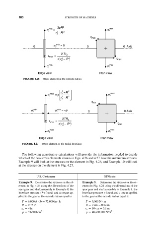
                     FIGURE 4.26  Stress element at the outside radius.
                                         r + R 2                    max
                                          2
                                  s t max  =  p  o                 s t
                                          2
                                         r − R 2
                                          o
                                                          t min
                         s r min      s r min  = –p     0                   0 Axis

                                          2TR
                                   t   =     o
                                   min
                                          4
                                        p  r  – R 4                     t min
                                          o
                                   max                              max
                                  s t                              s t
                              Edge view                        Plan view
                    FIGURE 4.27  Stress element at the radial interface.

                    The following quantitative calculations will provide the information needed to decide
                  which of the two stress elements shown in Figs. 4.26 and 4.27 have the maximum stresses.
                  Example 9 will look at the stresses on the element in Fig. 4.26, and Example 10 will look
                  at the stresses on the element in Fig. 4.27.


                            U.S. Customary                       SI/Metric
                  Example 9. Determine the stresses on the el-  Example 9.  Determine the stresses on the el-
                  ement in Fig. 4.26 using the dimensions of the  ement in Fig. 4.26 using the dimensions of the
                  spur gear and shaft assembly in Example 8, the  spur gear and shaft assembly in Example 8, the
                  interface pressure (P) found, and a torque ap-  interface pressure p found, and a torque applied
                  plied to the gear at the outside radius equal to  to the gear at the outside radius equal to
                    T = 6,000 ft · lb = 72,000 in · lb  T = 9,000 N · m
                    R = 0.75 in                        R = 2cm = 0.02 m
                    r o = 4in                          r o = 10 cm = 0.1 m
                    p = 9,650 lb/in 2                  p = 48,680,000 N/m 2
   193   194   195   196   197   198   199   200   201   202   203