Page 195 - Marks Calculation for Machine Design
P. 195

P1: Shibu
                          January 4, 2005
                                      14:25
        Brown.cls
                 Brown˙C04
                              U.S. Customary  COMBINED LOADINGS   SI/Metric       177
                              
        2 
                      
       2
                            Eδ     R                         Eδ      R
                        p =    1 −                        p =    1 −
                           2R      r o                       2R      r o
                                                                    9
                                     2
                                 6
                                                                        2
                           (30 × 10 lb/in )(0.0005 in)       (207 × 10 N/m )(0.00001 m)
                         =                                 =
                                 2 (0.75 in)                        2 (0.02 m)
                                        2


          2
                                  0.75 in                           0.02 m

                           × 1 −                             × 1 −
                                   4in                              0.1m
                           15,000 lb/in                      2,070,000 N/m
                         =         (1 − 0.035)             =           (1 − 0.04)
                             1.5in                              0.04 m
                                                                        2
                                   2
                         = (10,000 lb/in )(0.965)          = (51,750,000 N/m )(0.96)
                                  2
                                                                        2
                         = 9,650 lb/in = 9.65 kpsi         = 49,680,000 N/m = 49.68 MPa
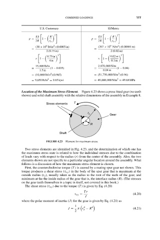
                    Location of the Maximum Stress Element. Figure 4.23 shows a press fitted gear (no teeth
                    shown) and solid shaft assembly with the relative dimensions of the assembly in Example 8.
                                 Stress elements  T
                                                       r o         Gear
                                                         R
                                        Shaft
                                 FIGURE 4.23  Element for maximum stress.
                      Two stress elements are identified in Fig. 4.23, and the determination of which one has
                    the maximum stress state is related to how the individual stresses due to the combination
                    of loads vary with respect to the radius (r) from the center of the assembly. Also, the two
                    elements shown are not specific to a particular angular location around the assembly. What
                    follows is a discussion of how the maximum stress element is chosen.
                      First, the counterclockwise torque (T ) is caused by a mating spur gear not shown. This
                    torque produces a shear stress (τ xy ) in the body of the spur gear that is maximum at the
                    outside radius (r o ), usually taken as the radius to the root of the teeth of the gear, and
                    minimum at the the inside radius of the gear that is, the interface radius (R). (The stresses
                    on the gear teeth themselves is a topic in itself, not covered in this book.)
                      The shear stress (τ xy ) due to the torque (T ) is given by Eq. (4.20)
                                                      Tr
                                                τ xy =                          (4.20)
                                                      J
                    where the polar moment of inertia (J) for the gear is given by Eq. (4.21) as
                                                 1     4  4
                                             J =  π r − R                       (4.21)
                                                     o
                                                 2
   190   191   192   193   194   195   196   197   198   199   200