
Page 190 - Marks Calculation for Machine Design
P. 190
P1: Shibu
January 4, 2005
Brown˙C04
Brown.cls
172
U.S. Customary 14:25 STRENGTH OF MACHINES SI/Metric
Step 4. Combine the shear stress due to the Step 4. Combine the shear stress due to the
torque (T AB ) from step 1 and the shear stress torque (T AB ) from step 1 and the shear stress
due to bending from step 3 using the expression due to bending from step 3 using the expression
in Eq. (4.13) to give in Eq. (4.13) to give
2 T AB 4 V 2 T AB 4 V
τ xy = + τ xy = +
π R 3 3 π R 2 π R 3 3 πR 2
= 3.8 kpsi + 0.2 kpsi = 4.0 kpsi = 36.7MPa + 1.5MPa = 38.2MPa
Step 5. Display the answer for the maximum Step 5. Display the answer for the maximum
shear stress (τ xy ) found in step 4, in kpsi, on the shear stress (τ xy ) found in step 4, in kpsi, on the
left stress element in Fig. 4.19. left stress element in Fig. 4.19.
0 0
4.0 38.2
0 0 0 0
4.0 38.2
0 0
As with the previous examples, this stress As with the previous examples, this stress
element diagram will be a starting point for the element diagram will be a starting point for the
discussions in Chap. 5. discussions in Chap. 5.
4.6 AXIAL AND PRESSURE
The fifth combination of loading to be considered as an axial load and a pressure load. This
type of loading is quite common in piping systems where a compressive or tensile preload
is placed on a section of pipe during installation and is in conjunction with the load due to
the internal pressure in the pipe. Pipe dimensions are typically based on internal diameter
with a standard wall thickness for each strength designation. As wall thicknesses of pipes
are small compared to the diameter, pipes can be considered to be thin-walled cylinders.
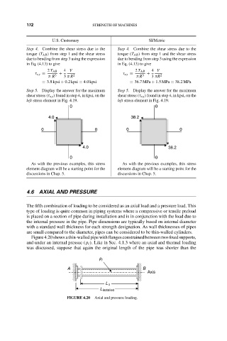
Figure4.20showsathin-walledpipewithflangesconstrainedbetweentwofixedsupports,
and under an internal pressue (p i ). Like in Sec. 4.1.3 where an axial and thermal loading
was discussed, suppose that again the original length of the pipe was shorter than the
p i
A B
Axis
L o
L installed
FIGURE 4.20 Axial and pressure loading.