
Page 186 - Marks Calculation for Machine Design
P. 186
P1: Shibu
14:25
January 4, 2005
Brown.cls
Brown˙C04
STRENGTH OF MACHINES
168
Starting with the top element, it is one of the two elements with maximum stresses, a
normal stress (σ xx ) due to the bending moment (M A ) and a shear stress (τ xy ) due to the
torque (T AB ). The normal stress (σ yy ) is zero.
The left element is the other element with maximum stresses, a shear stress (τ xy ) due
to the torque (T AB ) and an additional shear stress (τ xy ) due to the shear force (V ). Both
normal stressses (σ xx ) and (σ yy ) are zero, making this a pure shear element.
The bottom element is similar to the top element, except that the normal stress (σ xx ) is
compressive instead of tensile. Compressive is usually considered a lesser stress state than
tensile, which is why this is not a maximum stress element.
The right element is similar to the left element, except that the two shear stresses (τ xy )
are opposite to each other, whereas they are in the same direction on the left element. This
keeps it from being a maximum stress element.
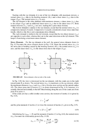
Stress Elements. For the top element at the wall, the general stress element shown in
Fig. 4.2 becomes the stress element shown in Fig. 4.18, where the normal stress (σ xx ) is
the stress due to bending caused by the bending moment (M A ), the normal stress (σ yy ) is
zero, and the shear stress (τ xy ) is the shear stress due to the torque (T AB ).
s yy 0
t xy t xy
t xy t xy M y
s xx s xx s xx = A max
→ I B
s xx Axis
t xy T r
t = AB max
xy
t xy t xy J
s yy 0
FIGURE 4.18 Stress element at the top side of the crank.
In Fig. 4.18, the view is downward on the top element, with the crank axis to the right
toward point B as shown. The normal stress (σ xx ) is maximum on the top element, where
the maximum distances (y max ) and (r max ) for a circular cross section are the outside radius
(R). The shear stress due to torsion (τ xy ) is shown downward in Fig. 4.18; however, it is
actually directed horizontally to the left when looking along the axis of the crank arm from
point B to point A.
If the crank arm has a solid circular cross section, the moment of inertia (I) is given by
Eq. (4.8),
1 4
I = πR (4.8)
4
and the polar moment of inertia (J) is twice the moment of inertia (I), given in Eq. (4.9).
1 4
J = 2I = πR (4.9)
2
Substituting for (y max = R) and the moment of inertia (I) in Eq. (4.8), the normal stress
(σ xx ) becomes the relationship given in Eq. (4.10).
M A y max M A R 4M A
σ xx = = 1 = 3 (4.10)
I π R 4 πR
4