
Page 189 - Marks Calculation for Machine Design
P. 189
P1: Shibu
14:25
January 4, 2005
Brown.cls
Brown˙C04
U.S. Customary COMBINED LOADINGS SI/Metric 171
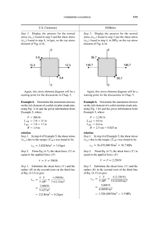
Step 5. Display the answers for the normal Step 5. Display the answers for the normal
stress (σ xx ) found in step 3 and the shear stress stress (σ xx ) found in step 3 and the shear stress
(τ xy ) found in step 4, in kpsi, on the top stress (τ xy ) found in step 4, in MPa, on the top stress
element of Fig. 4.18. element of Fig. 4.18.
0 0
3.8 36.7
15.3 15.3 146.7 146.7
3.8 36.7
0 0
Again, this stress element diagram will be a Again, this stress element diagram will be a
starting point for the discussions in Chap. 5. starting point for the discussions in Chap. 5.
Example 6. Determine the maximum stresses Example 6. Determine the maximum stresses
on the left element of a solid circular crank arm, on the left element of a solid circular crank arm,
using Fig. 4.16 and the given information from using Fig. 4.16 and the given information from
Example 5, where Example 5, where
P = 500 lb P = 2,250 N
L AB = 2ft = 24 in L AB = 0.8 m
L BC = 1ft = 12 in L BC = 0.4 m
R = 1.0 in R = 2.5 cm = 0.025 m
solution solution
Step 1. In step 4 of Example 5, the shear stress Step 1. In step 4 of Example 5, the shear stress
(τ xy ) due to the torque (T AB ) was found to be (τ xy ) due to the torque (T AB ) was found to be
2
2
τ xy = 3,820 lb/in = 3.8 kpsi τ xy = 36,670,000 N/m = 36.7MPa
Step 2. From Eq. (4.7), the shear force (V ) is Step 2. From Eq. (4.7), the shear force (V ) is
equal to the applied force (P) equal to the applied force (P)
V = P = 500 lb V = P = 2,250 N
Step 3. Substitute the shear force (V ) and the Step 3. Substitute the shear force (V ) and the
radius (R) in the second term on the third line radius (R) in the second term of the third line
of Eq. (4.13) to give of Eq. (4.13) to give
4 V 4 (500 lb) 4 V 4 (2,250 N)
τ xy = 2 = 2 τ xy = 3 πR 2 = 3 π(0.025 m) 2
3 πR 3 π(1.0in)
2,000 lb 9,000 N
= 2 = 0.00589 m 2
9.425 in
2
2
= 212 lb/in = 0.2 kpsi = 1,528,000 N/m = 1.5MPa